Welcome to Laser Pointer Forums - discuss green laser pointers, blue laser pointers, and all types of lasers

LPF Donation via Stripe | LPF Donation - Other Methods

Links below open in new window

ArcticMyst Security by Avery

DIY Homemade laser diode driver

Status
Not open for further replies.
Joined
Dec 4, 2008
Messages
10
Points
0
THANK YOU DDL FOR ALL YOUR HELPFUL INFORMATION ;D :) ;) :) ;) :cool:

My circuit now produces 300ma at about 3 volts, but i can regulate the current from about 20ma to 300ma. Im keeping it at 220ma and this gives me a voltage of 2.8v. I am just wondering when i test it out with an LED it works fine. When i measure the amps on it the LED cuts out. When i take the probes away the LED lights up again. If im testing this with a diode, will this be harmful to it. I am measuring the current parallel to the LED. Is this correct?

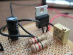
I have included a photo of the circuit. I tries to make it as small as possible.

Again thanks SOOOOO much

Fatboyslim
 

Attachments

  • IMG_7611.JPG
    IMG_7611.JPG
    92.2 KB · Views: 7,169


Joined
Dec 24, 2008
Messages
5
Points
0
I built the circuit but when I vary the resistance on the pot only the current changes. I am new to this and I don't solder very well. What do you think I am doing wrong? My resistor is 5 ohms and the pot is 25 ohms max. resistance. Also, what voltage and current is good for a PHR-803T diode?
 

daguin

0
Joined
Mar 29, 2008
Messages
15,989
Points
113
snapperhill said:
I built the circuit but when I vary the resistance on the pot only the current changes. I am new to this and I don't solder very well. What do you think I am doing wrong? My resistor is 5 ohms and the pot is 25 ohms max. resistance. Also, what voltage and current is good for a PHR-803T diode?


You are doing fine.  That's how it is supposed to work.  You only vary the current.  The diode pulls what voltage it needs (as long as you supply enough).  

The violet diode needs about 5V (plus whatever voltage your driver needs).  You're probably going to need to supply around 7.5V at a minimum from the power source.  For long life while still maintaining the ability to burn, adjust the current for your PHR diode to be about 120mA.  

Peace,
dave
 

daguin

0
Joined
Mar 29, 2008
Messages
15,989
Points
113
snapperhill said:
can I use 5 AA batteries?


5 x 1.5 = 7.5   :)

5 x 1.2 = 6  :(

One other thing to keep in mind. This is a "linear" driver. If you change the power supply significantly (like to 9V) you should re-check the current before hooking up the diode. Don't forget to short the cap before you hook up a diode.

Peace,
dave
 
Joined
Jan 20, 2008
Messages
1,724
Points
0
fatboyslim said:
I am measuring the current parallel to the LED. Is this correct?

Nope, you measure amperage in series with the circuit... ie: the meter completes the circuit.

Remember that if you disconnect and then reconnect your diode while the driver is under operation it will charge the capacitor and your diode will blow as it's reconnected. This is why most people don't measure amperage with an ammeter, but rather by putting a resistor of a known value in series with the diode, measuring voltage across the resistor, then using ohm's law to find the amperage. Most people throw in a 1ohm resistor, since the math becomes really simple. @1ohm, 1mV = 1mA.
 
Joined
Jan 15, 2009
Messages
1
Points
0
hi, i' m a newbie with laser. i want to built a burning laser with this diode - Sony SLD1239JL-54. I have a question. Why we need a variable regulator in the driver circuit? will we adjust that VR? For what? Thank you
 
Joined
Dec 2, 2008
Messages
339
Points
18
hello guys, i would try to build this driver, but i have no idea how to follow any scheme.. i dont know if i must lead wires like on the picture or i just need to solder everything together... ??????

it seems so simple as there is only few parts, so i would like to try this, but HOW??

sorry for stupid question, but i dont how to follow a scheme
 

Attachments

  • LM317_components01_00.jpg
    LM317_components01_00.jpg
    66.2 KB · Views: 60,560
Joined
Dec 2, 2008
Messages
339
Points
18
MilanTheOne said:
hello guys, i would try to build this driver but i have no idea how to follow any scheme.. i dont know if i must lead wires like on the picture or i just need to solder everything together... ??????

it seems so simple as there is only few parts, so i would like to try this, but    HOW??

sorry for stupid question, but i dont how to follow a scheme


i just would like to update it as i didnt metion that it could be for a Blu-ray
 
Joined
Jul 24, 2007
Messages
2,749
Points
0
The modified drawing is correctly blobbed with solder ;) You may want to replace the 2 resistors with one 10ohm resistor to set your max ma. The rest of the components are fine, as is the 9v battery.

Regards rog8811

[edit]This is in reference to some PM's that have gone back and forth, I thought it was worth adding to the thread as it makes laying out the driver nice and easy.

Get some veroboard,   http://cgi.ebay.co.uk/5-x-Copper-St...14&_trkparms=72:1298|66:2|65:12|39:1|240:1318
Cut it to size, push the components into the holes, as shown, one at a time and solder them in place, then move on to the next one.(the grey bit between the resistor and pot is a wire link)......Make sure all solder blobs look like the drawing for instance under the 100ohm pot you need to bridge the solder across to the next track.

I hope this helps, I cannot think of an easier way to show it.... :-/[/edit]
 

Attachments

  • 803T_vero_layout_LM317_driver_001.jpg
    803T_vero_layout_LM317_driver_001.jpg
    57.2 KB · Views: 5,480

poboy

0
Joined
Jan 22, 2009
Messages
5
Points
0
I went Radioshack and got some stuff to build the driver. please double check me please.
47uf cap
in4001 diode
pack of 5 10ohm resistors 1/2watt 5% tolerance
lm317T positive regulator
they didn't have a 100 ohm resistor so i got
1k ohm micro size potentiometer 50vdc .01 watts ?
1k ohm 15 turn cermet potentiometer .75 watts?
i scanned over the 50+ pages today at work and i thought some people have used the 1k resistors.
i'm ready to start building! ;D
 
Joined
Jul 24, 2007
Messages
2,749
Points
0
1k ohm micro size potentiometer 50vdc .01 watts ?
1k ohm 15 turn cermet potentiometer .75 watts?

Fine adjustment will be far harder with a 1k pot so you need to be extremely careful with the setup!
Drawing below shows the problem

Regards rog8811
 

Attachments

  • 1K_to_100R_001.jpg
    1K_to_100R_001.jpg
    37.7 KB · Views: 1,917

poboy

0
Joined
Jan 22, 2009
Messages
5
Points
0
Thanks!
I'm going to build a red first before i attempt the bluray! ;) which one would work better out of the 2? the 15 turn?
I will try and order some 100 ohm pots from radioshack.
 
Status
Not open for further replies.


Top