LPF Donation via Stripe | LPF Donation - Other Methods
Links below open in new window
ArcticMyst Security by Avery


You are using an out of date browser. It may not display this or other websites correctly.
You should upgrade or use an alternative browser.
You should upgrade or use an alternative browser.
DIY Homemade laser diode driver
- Thread starter Daedal
- Start date
- Status
- Not open for further replies.


I am guessing you mean 200mA.
Just adjust your pot until you have 200mA of output using your test load.
With two 10 ohm resistors the max output on your driver will be about 250mA.
If you want to set the max to 200mA there is a formula on the first few pages of
this thread that you can use to determine the ohms you will need for that.
Hope that helps.
Hi guys, btw, there is a website to calculate the value of the resistors.
Use a fixed resistor to set the UPPER limit of the current source. Lets call the R1.
The adjustable pot in SERIES with the above resistor ADDS to the total resistance from 0 (turned one end) to the value of the pot (turned the other end).
Lets call this R2.
So, the range of the resistance is actually from (R1 +0) to (R1+R2)
Here is the link to calculate resistor value for LM317:
http://www.reuk.co.uk/LM317-Current-Calculator.htm
- Joined
- Oct 5, 2008
- Messages
- 6
- Points
- 0
You could just add a very high value resistor in directly, 50k+ ohms.
It'll discharge the cap when the power is off in about 200-500 ms but will also give so much resistance that when the power is on 99.9% of the current will still go to the LD.
Also, yes, the switch will work")
It'll discharge the cap when the power is off in about 200-500 ms but will also give so much resistance that when the power is on 99.9% of the current will still go to the LD.
Also, yes, the switch will work
- Joined
- Oct 5, 2008
- Messages
- 6
- Points
- 0
Thanks
billg519
0
- Joined
- Feb 21, 2008
- Messages
- 1,056
- Points
- 0
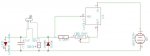
I always put a resistor in parallel with the capacitor. Anything above 470 ohms or so does not significantly affect the diode, and will always ensure that the capacitor is drained very quickly. I also use a 47uf cap across my diodes. (Noticed it in your schematic) Using this resistor, you won't kill a diode by forgetting to discharge the capacitor when you change over from test load to real diode.
- Joined
- Oct 5, 2008
- Messages
- 6
- Points
- 0
Not a bad idea
- Joined
- Oct 5, 2008
- Messages
- 6
- Points
- 0
I've got a problem,
when I turn the pot both the voltage and amperage go up (when the 100 ohm pot is at full I get a few miliamps and two volts however when I as I turn the pot the voltage and amperage clime to 3.9v and 300 mA). I am currently testing with an LED but I need this clarified before I move to a laser diode.
when I turn the pot both the voltage and amperage go up (when the 100 ohm pot is at full I get a few miliamps and two volts however when I as I turn the pot the voltage and amperage clime to 3.9v and 300 mA). I am currently testing with an LED but I need this clarified before I move to a laser diode.
Voltage is the force and amps is the flow, they are directly linked so will increase together which is normal. It is suggested to use a chain of diodes with a 1ohm resistor as a test unit as LEDs act differently to LDs and produce incorrect results.
With laser diodes the important one to monitor is the amps
With laser diodes the important one to monitor is the amps
- Joined
- Oct 5, 2008
- Messages
- 6
- Points
- 0
Thank you, I found the schematic a few pages back for the test diode and have a quick question: would a .975 ohm resistor work?
It can work.
The main reason for using a 1ohm was you can test the amount of current passing through it with a volt meter, 100mV across the resistor would mean 100mA through it.
Ohms law -> current = voltage / resistance
So with a 1 ohm resistor you'll always be dividing the voltage by 1 which would give an answer the same as the voltage.
You can still measure the amps with the .975 resistor but you'll need to do some math on your mV result, e.g.
250 mv / .975 ohms = 256.4 mA
- Joined
- Oct 5, 2008
- Messages
- 6
- Points
- 0
got it, thanks
- Joined
- Oct 12, 2008
- Messages
- 6
- Points
- 0
I built this circuit on a breadboard and am trying to test it on a LED but the LED never goes out even when turned to maximum resistance. WHATS WRONG? is my POT bad?
- Joined
- Oct 12, 2008
- Messages
- 6
- Points
- 0
ok, so i've got the DVM and am reading 5.83v on the leads meant for the LD. the value doesn't change when I turn down the POT also, I get NOTHING when
trying to get a reference voltage. please help :-X
trying to get a reference voltage. please help :-X
- Joined
- Feb 22, 2008
- Messages
- 3,182
- Points
- 48
wow thats a please ban me forum ID name if ever Iv'e seen one :-/
- Status
- Not open for further replies.
