Welcome to Laser Pointer Forums - discuss green laser pointers, blue laser pointers, and all types of lasers

LPF Donation via Stripe | LPF Donation - Other Methods

Links below open in new window

ArcticMyst Security by Avery

DIY Homemade laser diode driver

Status
Not open for further replies.
Joined
Jul 24, 2007
Messages
2,749
Points
0
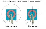
Adjusting a 1k pot in the low ohms area is going to be hairy.....I will try to find the drawing I did that shows the problem, I think it is on my work computer....will post it later..

Regards rog8811

[edit]Found it, the arrow shows the angle of turn required for 100ohms to zero ohms on the two pots, I hope it helps visualise the "fine setting" problem[/edit]
 

Attachments

  • turning_pot01_001.jpg
    turning_pot01_001.jpg
    100.4 KB · Views: 383


Joined
Sep 16, 2008
Messages
48
Points
0
Thanks for the diagram.

Ok so technically if i am operating my laser at 420ma then i wouldn't have to have a variable potentiometer if i am using a 3 ohm resistors. I don't plan to change the output at anytime.
So how would i hook up the circuit without the pot ?
 

Ace82

0
Joined
Feb 11, 2008
Messages
1,768
Points
0
trublu832 said:
Here's yet another version of the driver for a HD DVD laser with an lm317, a 25ohm pot, a 33ohm resistor,a 1N914 diode, and a 10uf cap. I'm also working on an SMD version of this board which will make this one look like a skyscraper  :D

I built this driver exactly to these specs for my HD DVD 405nm but I can't get it to the desired output power. I've tried tinkering with the componet set up and I believe it's the regulator. I'm giving it 3 x 3.6V, maybe I need to give it more voltage for the blu-rays? The pot works as it should, but just not the power I get from the rckstr. :-/
 
Joined
Jul 24, 2007
Messages
2,749
Points
0
I built this driver exactly to these specs for my HD DVD 405nm but I can't get it to the desired output power.
What is the max ma out you can measure from it Ace? Also have you measured the ref voltage to see if the reg is doing what it should?

Regards rog8811
 

Ace82

0
Joined
Feb 11, 2008
Messages
1,768
Points
0
The max mA is ~65 and no, I haven't measured the reg voltage.  Should I measure the output or the adjustable out? It should be 7.8 volts right?

Edit: over a year old and almost 1,000 replys, nice thread DDL! :D
 

Ace82

0
Joined
Feb 11, 2008
Messages
1,768
Points
0
Hey Rog, thanks for your persistance.  I did read that thread and I find it most helpful.  :) I'm using the 1N4001 not the 1N914, could that make that much difference?  
I see the input voltage is LD + 3, and then I see "6 for red & 9 for br" of coarse, that's including the +3 so the diode really needs 3 for red and 6 for br right?  That being said, I'll run the tests and make sure that everything is as it should be.  Thanks Rog, you never fail.  :)

Edit, I think I found the problem. I hooked up the pot per attached picture (in green) which I think could cause the problem.
 

Attachments

  • wrong_pot_connection.JPG
    wrong_pot_connection.JPG
    8.5 KB · Views: 264
Joined
Jul 24, 2007
Messages
2,749
Points
0
*Got it...I tried for the 500th post and failed....got the 1000 though :)*


Regards rog8811
 

Ace82

0
Joined
Feb 11, 2008
Messages
1,768
Points
0
rog8811 said:
*Got it...I tried for the 500th post and failed....got the 1000 though :)*


Regards rog8811

What if I delete one of my prior posts, will that make yours 999 and this one 1000?

Just kidding, you deserve it!

So what you think, that pot set up be my problem? What about the diode?
 
Joined
Jul 24, 2007
Messages
2,749
Points
0
So what you think, that pot set up be my problem? What about the diode?

Sorry I got lost in the moment :)
If the diode you are asking about is the reverse protection one I would doubt it is the problem....unless you have it the wrong way round :-/ ....why not remove the diode from the circuit and test again?

Regards rog8811
 

Ace82

0
Joined
Feb 11, 2008
Messages
1,768
Points
0
rog8811 said:
So what you think, that pot set up be my problem? What about the diode?

Sorry I got lost in the moment  :)
If the diode you are asking about is the reverse protection one I would doubt it is the problem....unless you have it the wrong way round  :-/  ....why not remove the diode from the circuit and test again?

Regards rog8811

Hey, You put in lots of repeatitive work around here helping us nonelectronicexperts here suceed! I did try removing the diode from the circut, and it acts the same. Did you see my attachment in the previous page where I connected the pot opposite how it should? I'll try it later the correct way, or is that not the problem? ;D (I just felt like laughing)
 
Joined
Jul 24, 2007
Messages
2,749
Points
0
I hooked up the pot per attached picture (in green) which I think could cause the problem.
Yes just seen the edit... the only effect that your wiring of the pot will have is that it will reverse the resistance....

Let me try that in English ;)
If you wire the wiper (in green) to one end of the pot turning the knob clockwise winds the resistance higher, wire the wiper to the other end of the pot and winding the pot clockwise takes the resistance lower so not the problem..... one thing to check, does the positive line to the LD come from the the adj pin of the regulator, it is easy to think it comes from the out (middle) pin.

Regards rog8811
 

Ace82

0
Joined
Feb 11, 2008
Messages
1,768
Points
0
Yes, in that case I've done everything right. I even thought of that avenue as well. hum, keep trying. I've built two and both act exactly the same. I'm sure I'll figure it out.
 

Galdor

0
Joined
Aug 31, 2008
Messages
61
Points
0
I had the same problem when I built my DDL driver. Turns out I had
misswired the pot and the regulator somehow. It took several reviews of
the diagram before I finaly figured it out. Just keep lookin it over and I am
sure you will find the problem. ;)
 
Joined
Jul 24, 2007
Messages
2,749
Points
0
Ace, could you post clear pictures of both sides of your circuit board, in the past we have been able to sort out the problem that way.

Regards rog8811
 

Ace82

0
Joined
Feb 11, 2008
Messages
1,768
Points
0
rog8811 said:
Ace, could you post clear pictures of both sides of your circuit board, in the past we have been able to sort out the problem that way.

Regards rog8811

Of coarse I will. :)
But, I must make another, since the two I've made has been experimented with isn't so pretty. I'll go for the 3rd. I will post pictures.
 
Status
Not open for further replies.


Top