Welcome to Laser Pointer Forums - discuss green laser pointers, blue laser pointers, and all types of lasers

LPF Donation via Stripe | LPF Donation - Other Methods

Links below open in new window

ArcticMyst Security by Avery

DIY Homemade laser diode driver

Status
Not open for further replies.

daguin

0
Joined
Mar 29, 2008
Messages
15,989
Points
113
Zom-B said:
[quote author=rog8811 link=1185701612/948#956 date=1215209749]LD_pin-out_003.jpg
I hate this diagram. It is extremely confusing, even for a laser diode expert.
[/quote]


How about this one?

LaserDiodePinout.jpg


Peace,
dave


Joined
Jun 16, 2008
Messages
2
Points
0
hi Daedal;

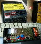
thanks for your help much; now i have time to take photos and let u see my circuit.  from figures it is a 200 mw it is rated 174ma but seems not as bright as so.
 

Attachments

  • laser_025.jpg
    laser_025.jpg
    189.2 KB · Views: 1,267
Joined
Jul 24, 2007
Messages
2,749
Points
0
Zom-B said:
[quote author=rog8811 link=1185701612/948#956 date=1215209749]LD_pin-out_003.jpg  
I hate this diagram. It is extremely confusing, even for a laser diode expert.
[/quote]

I promise never to post it again....as it is extremely confusing..... :)

Regards rog8811
 
Joined
Mar 19, 2008
Messages
33
Points
0
i just ordered a few components to create the circuit posted on the first post, with the intension of powering it with a 9v pp3 battery.
but i thought the lm317 would change every incoming voltage (say 9v) to  ~3v to drive the diode, but elsewhere i read that the lm317 won't change anything and it has a 3v drop-out(?)
so that you'll need 6v to drive a 3v diode.

is it possible to power it with a 9v battery? and maybe with 2x lm317's? 1 for the current and another for the voltage?
if so, has anyone a drawing for me?

another thing;
i've also read in this topic that the maximum output by this driver is ~317MA, i need 350MA for my diode, is this possible with the same components?
solved, i just need to change a resistor
 

Zom-B

0
Joined
Mar 25, 2008
Messages
895
Points
28
:cool: :cool: Congratulations on the Daedal driver. This thread is alive for exactly one year today. :cool: :cool:
 
Joined
Apr 29, 2008
Messages
1,562
Points
48
Ok, so I went to RadioShack today, and bought all of the supplies needed to make the DDL circuit to power my PHR-803T diodes. Once I got home, I realized that I got a 10K ohm 15-turn pot instead of a 25 ohm one. I thought that it shouldn't be a problem so I still built the circuit . For the resistor I used a 22 ohm one. Anyways, I hooked everything up and used some 1N4004 rectifier diodes to make a test. I used a 9 volt battery for the supply, and put my multimeter in series with the driver, and the reading on the multimeter was 22mA. I switched the resistor to a 12 ohm one, and the multimeter displayed 11mA. Even when turning the pot, only slight changes would happen. How come the current is so low? Should I get a lower ohm pot? If I want 100ma, what resistor do I need? (well, according to Syropyro's formula I would need a 12.5 ohm resistor, but I still am not getting close to 100ma.)

Thanks,
Jimmymcjimthejim

Edit:
I realized that I put the LM317T in backwards.. I'll flip it around and post what the results are.
Edit2:
I flipped the LM317T around and BAM! Everything works perfectly! I powered the violet laser to 100ma and IT IS DAM BRIGHT!
Edit3:
One of the leads connected to the legs of the diode disconnected and reconnected... Darn capacitors... :mad: :mad:
 
Joined
Aug 7, 2008
Messages
159
Points
0
So ya could I follow the entire scheme but use the 10k 15 turn pot instead of the 25ohm rheostat? The 25ohm is so huge and the 10k is nice and tiny. Help
 
Joined
Apr 29, 2008
Messages
1,562
Points
48
chaosfourever said:
So ya could I follow the entire scheme but use the 10k 15 turn pot instead of the 25ohm rheostat? The 25ohm is so huge and the 10k is nice and tiny. Help
Apparently it doesn't matter what kind of pot you use. For me, with the 10k ohm, it turns about 10 times, then in one turn it goes from about 10ma to 105ma (Which is my max) Then it just turns until it stops. Sorry if I confused anyone.
 
Joined
Aug 7, 2008
Messages
159
Points
0
ok I'm bad at wiring, but did you connect the vin on the pot to the vout on the lm317 and the used the center to go to the two resistors and left the third terminal un wired or did you connect the vin and center together and did the third to the two resistors?
 

rkcstr

0
Joined
Dec 1, 2007
Messages
1,368
Points
0
Ok, I'm going to try to help you better understand just exactly what you're doing:

A potentiometer is basically a resistor that is connected across the outer pins (pins 1 and 3), while the center pin (pin 2), that is called the 'wiper' is a metal contact that allows you to "tap" into that resistor, which is a conductive track of resistive material.  So, depending on where along that track it connects, it will produce different resistances between pin 1 and 2 and pin 2 and 3, where the the two resistances added together will equal the total resistance of potentiometer, and they change proportionally as you turn to equal that total resistance (ex in the middle a 10k pot will be 5k on one side, 5k on the other, turn it to 3/4 it will be 7.5k on one side, 2.5k on the other, etc).

So, to use it how you need, you're actually going to connect it as a 'variable resistor' rather than a 'potentiometer', which is typically a voltage divide (don't worry bout that).  So, you're going to connect pin 1 of the VR (variable resistor) to the vout (pin 1) of the LM317, Pin 2 and 3 can be connected together (essentially you just need pin 2 connected, but shorting it to pin 3 is standard practice for a variable resistor setup) and then soldered to the resistor which limits your maximum output current.

Also, just to point out, all pots/trimmers/variable resistors have a minimum resistance (ie no 0 ohms), which could be up to a few ohms for the high resistance pots, so that may influence your maximum output current setting. But for those multi-turn, they may have lower minimum resistance than the standard single-turn ones.
 
Joined
Aug 7, 2008
Messages
159
Points
0
OK then So which variable resistor should I get at Radioshack? Be very specific please. Can I get the 10k 15 turn? I just want it to be as tiny as possible.
 
Joined
Sep 12, 2007
Messages
9,399
Points
113
The 10k[ch937] would have a greater effect per turn if you were to add a resistor in parallel. The formula is:

1 1 1 1 1
__ + __ + __ + __ ...etc. = __

R[sub]1[/sub] R[sub]2[/sub] R[sub]3[/sub] R[sub]4[/sub] R[sub]T[/sub]


For example, 10k[ch937] in parallel with a 10k[ch937] resistor would yield an effective range of 0-5k[ch937]. 10k[ch937] with 101[ch937] would yield 0-100[ch937] which is the number I hear floating around here quite a bit.
 
Joined
Aug 7, 2008
Messages
159
Points
0
cool so ill use the original diagram with the 2 10ohm on page 1 and then get a 1k 15 turn from radioshack. This will be tiny.
 
Joined
Aug 7, 2008
Messages
159
Points
0
OK thx for all the help. Now for my new problem. I wanna mod my stuff into a flashlight so I can use it as a nice pointer. Yet it seems I need the CR123 batteries. Do these fit into a regular flashlight? Any suggestions on a flashlight that I can use, and not the dorcy mini since I am following this sheme and making the driver stuff myself. Anyone help please?
 
Joined
Aug 7, 2008
Messages
159
Points
0
OK so I still need help with my post above here, but also as a side note I was wondering if I can sholder directly on the board such as on page 47 instead of using wiring because I do want this to be as small as possible.
 
Status
Not open for further replies.


Top