Welcome to Laser Pointer Forums - discuss green laser pointers, blue laser pointers, and all types of lasers

LPF Donation via Stripe | LPF Donation - Other Methods

Links below open in new window

ArcticMyst Security by Avery

DIY Homemade laser diode driver

Status
Not open for further replies.

Daedal

0
Joined
May 23, 2007
Messages
2,277
Points
0
rog8811 said:
@ DDL I have built the power supply to your design...except that my VR is 200ohm and the series res is 4.4ohm. :)

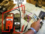
When I power it with 6 volts it lights an led, at lowest setting, with a measured output of 4.63v @ 6.5ma
turning the pot to other end of scale... the led doesn't appear to get brighter and I measure 5.84v @ 36ma

Does any of that look right?

Regards rog8811

Just thought I am using a 1n4148 diode, but that should only effect things on reverse polarity.


First off, glad you got the parts and the VR and the R-block (as I like to call it), sound perfectly fine. I assume you know the max possible by the circuit with a 4.4-Ohm, it's about 284mA.

I would check 2 things... First of all make sure you have plugged the LM317 in right, that you plugged things into it right, and that you didn't mix up the Vout and the Adj poles. (remember that on the LM317T the big heat sink is linked to the Vout, and you can connect using it.) Second, try to take everything out, the LED's the 1N4148 and anything past the point where the Adj and the Vout lines meet (after the VR and R-block) and connect a DMM in there to make sure the circuit is wired right. Simply connect the red DMM pole to the junction and the Black pole to ground. If you see current flowing through then your connection is right, otherwise then you have wired the LM317 the wrong way or you have a dead LM317.

Hope this helps;
DDL


Joined
Jul 24, 2007
Messages
2,749
Points
0
@DDL Thanks for the info, it turned out that my 2 meters were interacting, first supply built and driving my greenie! :) Just need to wait for the modules from SenKat to do part two. I still find that with my fluke in line measuring the ma the greenie will not lase, Is that normal?

Regards rog8811
( I will delete these enquiry posts to clean up the thread in a couple of days)
 

Daedal

0
Joined
May 23, 2007
Messages
2,277
Points
0
Rog, do not bother deleting the posts. It is actually much better the way it is considering the different questions and the answers that have been provided.

As about the green laser, what mA is your green laser getting? what power green laser is it? Remember that when measuring current the power MUST pass THROUGH the DMM, and when measuring the voltage the DMM MUST be ACROSS the circuit. If you are getting erroneous results let us know or just post some pictures and I will tell you exactly how to get it working.

On a second note, you say that you are driving your green laser with this, but I am sorry to tell you that this circuit will need a little more work to make it capable of driving a green laser (IR diode powerful enough to lase green).

I hope this helps;
DDL
 
Joined
Jul 24, 2007
Messages
2,749
Points
0
DDL, I should say the drive circuit is driving the built in drive circuit of the 10mw green. I will put the meters back on tomorrow, but the way it is working at the moment is that if I have the meter in circuit the greenie will not lase. with the meter out I can wind up the pot and on comes the greenie.

I am probably doing something wrong but at least things seem to be working.

Regards rog8811
 
Joined
Oct 24, 2006
Messages
2,032
Points
0
rog8811 said:
DDL, I should say the drive circuit is driving the built in drive circuit of the 10mw green. I will put the meters back on tomorrow, but the way it is working at the moment is that if I have the meter in circuit the greenie will not lase. with the meter out I can wind up the pot and on comes the greenie.

I am probably doing something wrong but at least things seem to be working.

Regards rog8811

Just a guess but for powering a greenie driverboard like that you may want to configure it as a voltage regulator instead of a current regulator.
 
Joined
Jul 24, 2007
Messages
2,749
Points
0
OK, this is where you tell me that my greenie is on borrowed time, I put the meters back on  without resetting the the pot....the greenie does lase but not as brightly.

With a 6volt input I am measuring 4.32 volts between ground and the reg heatsink and with the other meter in the positive line between the circuit board and the laser unit I am seeing 227.3ma...Out of interest I did reduce the resistor to 2.2ohm between my first question on this subject and getting it working.

As photbucket is under maintainance at the moment I have not been able to upload the photo, I have noticed the attach bit at the bottom of this dialogue box....i wonder :)
 

Attachments

  • meter_setup01.jpg
    meter_setup01.jpg
    302 KB · Views: 1,682
Joined
Oct 24, 2006
Messages
2,032
Points
0
So you're running 4.32V though a greenie thats made for 3V? Sounds pretty risky if you ask me. Daedal's circuit is a current regulator - not really what you want to use for powering the driverboard of a greenie. Its equally easy to modify your circuit though to be a voltage regulator (aim for a voltage of ~3.0-3.1V).

I'd suggest you go here: http://www3.national.com/ds/LM/LM117.pdf and check out figure 1 on page 8 that shows you the basic design of the voltage regulator. Use a ~240 ohm resistor for R1 and then the voltage should be around 1.25*(1+R2/R1), so perhaps use ~360ohms (perhaps a resistor+pot) for R2.

(I know very little about electronics so someone please correct me if I'm completely screwed up here)
 

chimo

0
Joined
Jun 20, 2007
Messages
650
Points
0
When measuring current in the mA range DMMs drop a fair bit of voltage because the internal "sense resistor" is much larger than when on the 10A range. When inserted into the circuit lilke this, the DMM can often make a fairly high impact on the operation of the circuit.

For instance, in this example, IF the DMM's enternal sense resistor for the 200mA range is 2 ohms, the voltage dropped across it would be 0.45V (not counting any losses in the test leads).

Just food for thought.
 

Daedal

0
Joined
May 23, 2007
Messages
2,277
Points
0
Both are in fact very logical explanations and solutions. What I would like to know though is why would you use a regulator to power a laser that already has a drive circuit. :-? Is it maybe because you're trying to save batteries? or are you trying to make it into a lab-style laser powered via AC mains? If that is what you're trying to do, you really don't need to do most of this if you just use a regulated power supply. With any reasonable regulation from any of the power supplies from walwart or whatever, the drive circuit should also have the intelligence built in to filter out most of the signal imperfections after that (initially most of them spike rather high, and their current rating is not really that effective).

Perhaps I missed the focus of what you want to use this circuit for, but if you would explain it to us I'm sure we would come up with a more viable solution.

Thank you;
DDL
 
Joined
Jul 24, 2007
Messages
2,749
Points
0
OK all, this has been a bit of a hotch potch of bits of info on my project, so let me lay out what I am hoping to do.  :)

I am puting together a laser projector for use out in the woods and to be powered by a 12volt car battery.
It consists of a 10mw greenie and SenKat group buy red + combining prism for yellow (built) +liquid sky (built) + tunnel scanner (built) +spiro effect (built).

I have 2 stabilised power supplies that run from 12volt (car battery) and output 3/4.5/6/9/12volts @1500ma.

One with a split feed will supply 12v & 4.5v to run fans, speed controls and servos.

The other was always destined to supply the illumination,  I wanted to do away with the batteries in the lasers, (the red was to be an atlasnova 5 mw). Having purchased a couple of the group buy reds I set too to build a power supply, to DDL's design...ish....( the fixed resistor being 2.2ohm due to my collection of resistors having nothing else under 100+ ohms.)

I then thought why not build 2 circuits on the one piece of vero and run the greenie, though the greenie has its own built in circuit already, and the red from one board. That is where I am at the moment .

I am very happy to be advised by more experienced forum members, my problem Is I am ok with the practical/mechanical/electrical bits of engineering but the moment it gets to v=i/r and making sense of graphs on data sheets I just lose the plot. :)


@ DDL Sorry to muddy the waters, I think I should have started a new thread when I started using your circuit for something it wasn't designed to do.

@ pseudonomen I have now printed the data sheet off and will try to make sense of it.

@ chimo, If I read that correctly would it explain why the output of the greenie is less? ie the meter measuring the ma is dragging the output voltage down ......

Regards rog8811
 

chimo

0
Joined
Jun 20, 2007
Messages
650
Points
0
rog8811 said:
@ chimo, If I read that correctly would it explain why the output of the greenie is less? ie the meter measuring the ma is dragging the output voltage down ......

Regards rog8811

rog, if you use the 10A range, it will introduce much less loss when inserted in the loop.

You can also measure the voltage drop across the 2.2 ohm resistor and calculate the current (measure the resistance to get a more accurate figure - you DMM leads will also be added to this figure so if your DMM has an "absolute resistance" feature (DMM essentially subtracts the lead resistance) use it. The current will be I = V (measured) / R (2.2).

Paul
 

Gazoo

0
Joined
Jun 9, 2007
Messages
3,206
Points
38
Rog,
I have one of those adapters you are referring to. Mine is a Radio Shack and has a switching DC to DC converter built into it, so the voltage output will remain precise. Therefore, all you really need to do is set it to the 3 volt setting to power your greenie, and the diode from SenKat's GB.

For the diode all you need is a resistor connected in series with the power supply. If using 3 volts, a 1 Watt, 1 ohm resistor should work our well. Then connect a capacitor in parallel with the diode as shown in Daedal's circuit. The value of the capacitor is not critical, but should be at least the same as the one Daedal is using. This would be the easiest way.
 

Daedal

0
Joined
May 23, 2007
Messages
2,277
Points
0
Rog,

It seems like you have a very nice plan going there. IT also seems like you have already mane most of the plans for what you need it to do. Let me start off by saying that both of the suggestions by Gazoo and Chimo are very excellent suggestion. Measuring the current through resistor voltage is much better than to run the current through the DMM. Also, for the green laser, if you supply the 3V @ 1.5A from the adapter you have, the green pointer you have should be very happy. One more thing I'd like to know though. Are you referring to the GB of the >200mW red pointers, or the laser diodes? If you want to use the red pointers, then you have to provide that pointer with 6V and it will be fine. If you are trying to use the diodes then you can either try and use what Gazoo is suggesting, or you can use a regulated supply circuit such as this one.

Please also be advised to that I am working on a very similar circuit that runs off 3V and works just as well as this one. It is a little more expensive, but I believe it is much more worth it.

I hope this helped;
DDL
 
Joined
Jul 24, 2007
Messages
2,749
Points
0
@ Gazoo & Daedal.....Funny thing is when I knew nothing I was going to connect up both lasers to the DC/DC supply at 3volts, then had doubts that it was as simple as that. :)

I am buying the LD's not the pointer so a 1watt 1ohm resistor goes on my shopping list, I already have spare 10mf caps so that could be job done....having said that I will look out for your new circuit DDL as half the fun is in the building and experimentation.

Regards rog8811
 

Gazoo

0
Joined
Jun 9, 2007
Messages
3,206
Points
38
Rog I agree with you. It is fun to build these circuits and there is much we can learn from doing do. I am experimenting with Daedal's circuit and actually am powering it with the Dc to Dc switching adapter. I have it plugged into a 12 volt power pack. Now that I have finally gotten it into my head that Daedal is using the LM317 as a current regulator vs. a voltage regulator...lol, I am finding the circuit to work very well. I don't have my diodes yet from the GB so I am using a light bulb instead until the diodes get here. Once I receive the diodes I will report back here with more info. But so far I have found the current remains the same applied to the light bulb with any voltage of 4.5 volts or more. All I have hooked up so far is the LM317 and a resistor..lol. I need to get a decent trim pot to be able to get this circuit to work like I want it to, and then of course add the rest of the components to the circuit.
 
Joined
Jul 28, 2007
Messages
61
Points
0
Daedal,

Thanks for sharing your circuit, but I have a couple of quick questions. Suppose I wanted to just run a diode with the simplest configuration possible, 6 v power pack with dropping resistor and switch to diode. However, I still want to protect the diode from spikes, etc. Couldn't I just place the 47 uF cap across the diode along with the silicon diode for protection? Would I need anything else? The reason I'm asking is because I read somewhere that some protection circuits also have a resistor placed across the laser diode terminals, although I'm guessing that the silicon diode might serve nearly the same purpose.

Thanks in advance,
Jon
 
Status
Not open for further replies.


Top