Welcome to Laser Pointer Forums - discuss green laser pointers, blue laser pointers, and all types of lasers

LPF Donation via Stripe | LPF Donation - Other Methods

Links below open in new window

ArcticMyst Security by Avery

DIY Homemade laser diode driver

Status
Not open for further replies.

Gazoo

0
Joined
Jun 9, 2007
Messages
3,206
Points
38
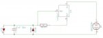
It's closer to 2 volts. If you are not applying at least 6 volts to the circuit it can do all kinds of crazy things, as I found out in my testing. 4 AA batteries won't cut it because the voltage will drop once you put a load on them.


Joined
Sep 12, 2007
Messages
207
Points
0
the data sheet I downloaded showed a diagram of the pins for the nte956 and they are the same config as the lm317t you used. (but I do plan on hitting RS to see if I can get one tonight) \

sh!t I think I was reading the voltage form the leads.... *kicks self* this is why you don't make circuits at 2am =)

ok so I should measure the voltage across one of the resisters or connecting wires in the circuit then yes? because I know I did that and if I remember right(again it was 2am) I was getting 1.8v so that makes more sense from the numbers in your original post meaning i'm getting about 1.25v drop like i'm supossed to.

(speeds up the clock so he can go home)

thanks again for the help, i'll let you know if the nte956 gives me the same readings as the lm317t, for those that are curious I got it from fry's Electronics(Arizona) all they carry is NTE base products. I got lucky I didn't know this going in and I guessed at which regulator would be a close match and when I checked it when I got home it was their exact replacement.
 

Daedal

0
Joined
May 23, 2007
Messages
2,277
Points
0
Archane, try putting 4 X 1N4001 diodes as your "load". That will create a voltage drop of ~2.8V which will let you simulate the presence of the LD. :)

GL;
DDL
 
Joined
Sep 12, 2007
Messages
207
Points
0
lol now there's an idea I didn't think of. i'll pick up 2 more then i'm down to 2 right now. christ I have been out of component work way too long.
 
Joined
Sep 1, 2007
Messages
1,591
Points
0
hey daedal i was wondering what is the voltage of an LD from the SenKat GB and also instead of a driver can i just use a current limiting resistor and a 3v power supply? will it kill my Diode?
with 2.8v to make 225-250 ma i need a 1ohm resistor so i can stick it in a flash light so will that work
 

Daedal

0
Joined
May 23, 2007
Messages
2,277
Points
0
toked323, I've actually got nothing to say to that other than... Good luck :)

I believe the topic has been discussed and concluded many times. ;D

Sorry;
DDL
 
Joined
Sep 6, 2007
Messages
51
Points
0
Can someone tell me if this checks out?

I built the circuit on a breadboard using the prescribed LM317, 47µF capacitor, and the 1N4001 diode.  After testing the circuit with a 10[ch8486] resistor and 1K[ch8486] 15 turn pot (the best small pot at the local Radio Shack), I found that the settings were pretty good at around 25[ch8486], so I took out the 10[ch8486] resistor and pot and put in a 22[ch8486] resistor.  I ran it off a 6V alkaline camera battery (RS's equivalent of a Duracell 4LR44 - tiny for small cases but only 105mAh) and through a regular LED, and testing at the LED I'm reading 2.45V and 57mA, which means it's got 43.9[ch8486] of resistence and 142.5mW.  Does this sound correct?  [smiley=thumbup.gif]?  [smiley=thumbdown.gif]?  I wanna make sure it's good so I can go ahead and put it all together on a PCB and get it fitted for a flashlight so I'm mostly ready to go when I get my diodes and Aixiz modules. ;D ;D ;D

Hopefully it's good.  Thanks for the help in advance!
 

Daedal

0
Joined
May 23, 2007
Messages
2,277
Points
0
Mountaineer, can you supply a picture of your circuit? :-?

That doesn't sound right to me from all the way here... ;D

--DDL
 
Joined
Aug 16, 2007
Messages
40
Points
0
Mountaineer said:
Can someone tell me if this checks out?

I built the circuit on a breadboard using the prescribed LM317, 47µF capacitor, and the 1N4001 diode.  After testing the circuit with a 10[ch8486] resistor and 1K[ch8486] 15 turn pot (the best small pot at the local Radio Shack), I found that the settings were pretty good at around 25[ch8486], so I took out the 10[ch8486] resistor and pot and put in a 22[ch8486] resistor.  I ran it off a 6V alkaline camera battery (RS's equivalent of a Duracell 4LR44 - tiny for small cases but only 105mAh) and through a regular LED, and testing at the LED I'm reading 2.45V and 57mA, which means it's got 43.9[ch8486] of resistence and 142.5mW.  Does this sound correct?  [smiley=thumbup.gif]?  [smiley=thumbdown.gif]?  I wanna make sure it's good so I can go ahead and put it all together on a PCB and get it fitted for a flashlight so I'm mostly ready to go when I get my diodes and Aixiz modules. ;D ;D ;D

Hopefully it's good.  Thanks for the help in advance!

22 [ch8486] ?? :eek:  hmm i am using a 5 [ch8486]. :-?

to DDL. you used a 5[ch8486] resistor to get the best out of the LD right??  :-?
 

Gb1k

0
Joined
Sep 17, 2007
Messages
1
Points
0
I'm new to this forum, i registered today to get some help building the driver.
I first put everything together matching EXACTLY as it appears on the color picture. Only difference is that i used a 25Ohm Pot.
I got no light on the LD at all.
I then changed the 4 AA's to 2xCR123 and paralleled the 10 ohm resistor with another 10 ohm then the LD started working but we're talking cheap laser pointer quality light. I have 3 LD's 2 of which i pulled out of a 16X DVD drive and 1 i bought online. 1 of the 3 i blew out by playing, but the other 2 LD's are still good. I use the blown out one for testing. Anyway here is where i'm stuck. NO POWER with neither LD's.

I suppose i should mention the obvious before anyone asks. I have 6.2V input from the batts, and 2.8 to the LD. I have no way to test the current so i can't get a read-out what is going in the LD exactly.

Please give me pointers what i can do different.
 
Joined
Sep 6, 2007
Messages
51
Points
0
Since I'm at work then have class, I can't post a picture just yet, so here's a hijacked and adjusted version of your circuit diagram.  I believe it's a 28mA red LED I have the circuit attached to, but I can let you know for sure once I'm home. Also, I was testing the circuit with my DMM at the LED.
 

Attachments

  • modded_LD_Driver_Schematic.JPG
    modded_LD_Driver_Schematic.JPG
    27 KB · Views: 3,034

Daedal

0
Joined
May 23, 2007
Messages
2,277
Points
0
Gb1k said:
I'm new to this forum, i registered today to get some help building the driver.
I first put everything together matching EXACTLY as it appears on the color picture. Only difference is that i used a 25Ohm Pot.
I got no light on the LD at all.
I then changed the 4 AA's to 2xCR123 and paralleled the 10 ohm resistor with another 10 ohm then the LD started working but we're talking cheap laser pointer quality light. I have 3 LD's 2 of which i pulled out of a 16X DVD drive and 1 i bought online. 1 of the 3 i blew out by playing, but the other 2 LD's are still good. I use the blown out one for testing. Anyway here is where i'm stuck. NO POWER with neither LD's.

I suppose i should mention the obvious before anyone asks. I have 6.2V input from the batts, and 2.8 to the LD. I have no way to test the current so i can't get a read-out what is going in the LD exactly.

Please give me pointers what i can do different.

Tell me what the resistance you are using is, and what voltage across that resistance you are getting. That will tell you what the current is :)

I would suggest 5-Ohm resistance for best results. Also, make sure you;re not staring into the IR LD. :eek: It'll show up as a weak 5mW red LD but it is actually much more powerful.

--DDL
 
Joined
Sep 6, 2007
Messages
51
Points
0
Here are the pics of my circuit.  I have it running a 5mm, 2.6V, 28mA LED.

The first one is just of the circuit powering the LED.  The battery is on the right out of the picture.

The second is of it the voltage measured on my DMM with the leads at the LED.  It's showing 2.339V (the battery is quickly dropping in voltage it was at about 2.45V last time.)  Measured like this, the current is 57mA.

The third picture is of the current being measured straight from the circuit without being connected to the LED.  Like this, it's at 57mA and 4.63V.

I figure I'm supposed to measure it with it hooked up to the LED?!?!  If that's right, then I'm getting ~41[ch8486] (2.339V/.057A) and 133mW (2.339V*.057A).  Does the rest of the circuit besides the resistor create about 19[ch8486] of resistence (41-22) :-??  If anyone has any questions/suggestions that could help me out on this or if you need more pictures, let me know, I need all the help I can get. I can answer your questions/post more pics in a couple of hours if needed (I have to get some mergers & acquisitions homework done - ouch! [smiley=cry.gif]) Thanks in advance.
 

Attachments

  • Circuit2.JPG
    Circuit2.JPG
    84.2 KB · Views: 4,413
Status
Not open for further replies.


Top