

jib77
0
- Joined
- Jun 19, 2010
- Messages
- 718
- Points
- 0
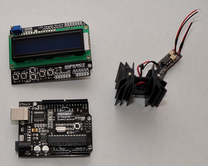
The pieces:
10x10mm TEC mounted on a TO220 heatsink and connected to a LM358 Amp circuit per this thread:
DIY Thermal LPM for under $50
Aduino Board:
DFRobot DFRduino USB Microcontroller (ATMega168) - RobotShop
DFRobot LCD/Keypad Shield:
DFRobot LCD Keypad Shield for Arduino - RobotShop
Assembly:
Amp Out+ => Arduino Analog input Pin1
Amp Out- => Arduino Analog input Pin2
Amp PWR+ => Arduino +5V Pin
Amp GND => Arduino GND Pin
Assembled with my sketch running:
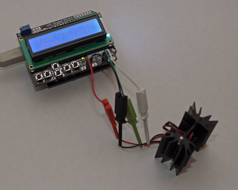
The Analog input has only 10bit resolution for 0-5V, this means roughly 5mV per bit, which is not great but good enough for me. I could use the internal reference voltage and get about a 2mV per bit resolution, but this makes the keypad unusable since it uses Analog Pin0 assuming a 5V Vref. I am going to try redefining the keypad trigger values for the internal Vref at a later date.
The Select button starts the LPM sampling. Left starts dumping the LPM reading every second over the serial port so I can capture it in a terminal app to create a log. Right stops the data dump. Up resets the Max to zero and Down stops the LPM sampling. Reset is just a relocation of the reset on the Arduino board for convenience.
Here is a video of it in action. I still need to calibrate the amp as I don't have any metered lasers or calibrated LPMs.
10x10mm TEC mounted on a TO220 heatsink and connected to a LM358 Amp circuit per this thread:
DIY Thermal LPM for under $50
Aduino Board:
DFRobot DFRduino USB Microcontroller (ATMega168) - RobotShop
DFRobot LCD/Keypad Shield:
DFRobot LCD Keypad Shield for Arduino - RobotShop
Assembly:
Amp Out+ => Arduino Analog input Pin1
Amp Out- => Arduino Analog input Pin2
Amp PWR+ => Arduino +5V Pin
Amp GND => Arduino GND Pin
Assembled with my sketch running:
The Analog input has only 10bit resolution for 0-5V, this means roughly 5mV per bit, which is not great but good enough for me. I could use the internal reference voltage and get about a 2mV per bit resolution, but this makes the keypad unusable since it uses Analog Pin0 assuming a 5V Vref. I am going to try redefining the keypad trigger values for the internal Vref at a later date.
The Select button starts the LPM sampling. Left starts dumping the LPM reading every second over the serial port so I can capture it in a terminal app to create a log. Right stops the data dump. Up resets the Max to zero and Down stops the LPM sampling. Reset is just a relocation of the reset on the Arduino board for convenience.
Here is a video of it in action. I still need to calibrate the amp as I don't have any metered lasers or calibrated LPMs.


")
