Welcome to Laser Pointer Forums - discuss green laser pointers, blue laser pointers, and all types of lasers

Buy Site Supporter Role (remove some ads) | LPF Donations

Links below open in new window

FrozenGate by Avery

DIY Arduino LPM

jib77

0
Joined
Jun 19, 2010
Messages
718
Points
0
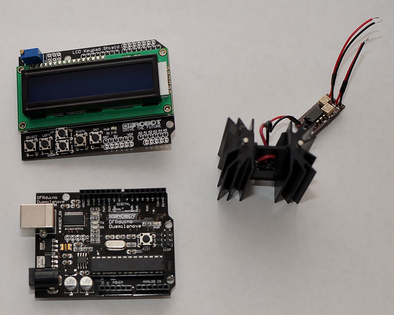
The pieces:

10x10mm TEC mounted on a TO220 heatsink and connected to a LM358 Amp circuit per this thread:
DIY Thermal LPM for under $50

Aduino Board:
DFRobot DFRduino USB Microcontroller (ATMega168) - RobotShop

DFRobot LCD/Keypad Shield:
DFRobot LCD Keypad Shield for Arduino - RobotShop


Assembly:

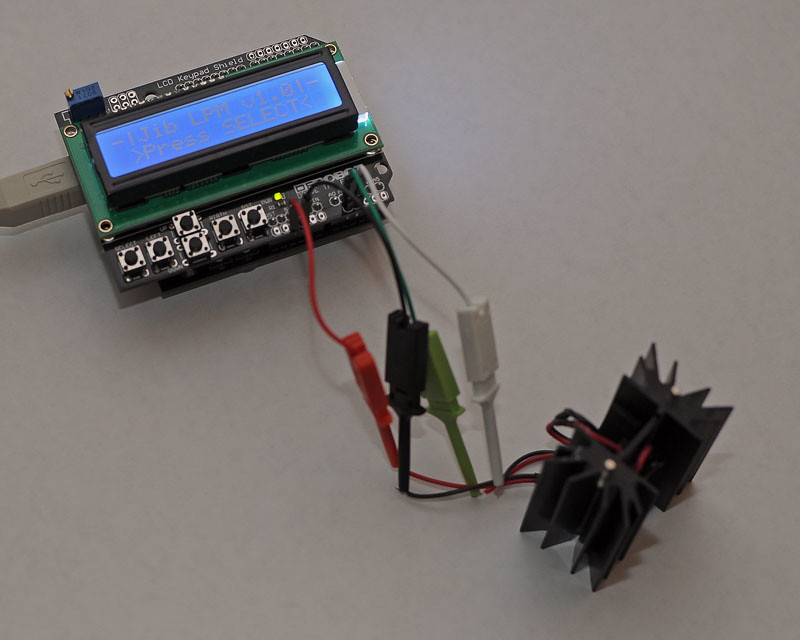
Amp Out+ => Arduino Analog input Pin1
Amp Out- => Arduino Analog input Pin2
Amp PWR+ => Arduino +5V Pin
Amp GND => Arduino GND Pin

Assembled with my sketch running:

The Analog input has only 10bit resolution for 0-5V, this means roughly 5mV per bit, which is not great but good enough for me. I could use the internal reference voltage and get about a 2mV per bit resolution, but this makes the keypad unusable since it uses Analog Pin0 assuming a 5V Vref. I am going to try redefining the keypad trigger values for the internal Vref at a later date.

The Select button starts the LPM sampling. Left starts dumping the LPM reading every second over the serial port so I can capture it in a terminal app to create a log. Right stops the data dump. Up resets the Max to zero and Down stops the LPM sampling. Reset is just a relocation of the reset on the Arduino board for convenience.

Here is a video of it in action. I still need to calibrate the amp as I don't have any metered lasers or calibrated LPMs.


Looking Good. :) Is this a Plug and Ply setup or is there some kind of programing that needs to be done in order to get it to work as a LPM and if so Is it Hard to Program it.?
 
This seems to good to be true, way to go ;)

Thanks! Recognize the wire on the amp board? :)

Looking Good. :) Is this a Plug and Ply setup or is there some kind of programing that needs to be done in order to get it to work as a LPM and if so Is it Hard to Program it.?

It does take programming ... its easy for me b/c my real jorb is embedded programming. But the Arduino IDE does make it as easy as possible if you know C.
 
This is a similar set up to the kenometer, tho Ken has specific software written fro his.

His uses an Arduino board as well, you'll need to download FTDI drivers (freely available via google) .

Wonder if it'll run Luminosity?
 
This is a similar set up to the kenometer, tho Ken has specific software written fro his.

His uses an Arduino board as well, you'll need to download FTDI drivers (freely available via google) .

Wonder if it'll run Luminosity?

His has a really nice parallel LCD screen that you can do graphics on. This is a serial screen limited to text. Also Im sure his Vref is set up for maximum resolution.

The driver needed is the Virtual COM Port Driver for the FT232-RL chip.

What is Luminosity? I couldn't find anything about it relating to Arduino.
 
I happen to have an arduino and an lcd like that. might give it a go sometime. thanks

EDIT: not.. I need the robot shield too, right ?
 
Last edited:
EDIT: not.. I need the robot shield too, right ?

Nah ... all you need is your arduino and display. That just happens to be RobotShop's clone of the Arduino ... I got that one since it was cheaper and I was getting their display/keypad combo shield.

Different versions of Arduino boards have different Vrefs depending on its I/O operating voltage, so adjust accordingly.
 
I'm curious, why not use an external ADC instead of an op amp? Something like a TI ADS1114 for example - 16 bit resolution, +/- 256 mV full scale (w/ gain set to 16). I2C interface. Mount it on the heat sink.

William
 
Last edited:
I'm curious, why not use an external ADC instead of an op amp? Something like a TI ADS1113 for example - 16 bit resolution, +/- 256 mV full scale (w/ gain set to 16). I2C interface. Mount it on the heat sink.

William

The op-amp circuit is used to convert the *tiny* voltages generated by the TEC to a more usable level ... once calibrated to 1mV = 1 mW you only need a DMM to get your reading. That being said I was thinking of adding a higher resolution ADC after the op-amp.
 
The op-amp circuit is used to convert the *tiny* voltages generated by the TEC to a more usable level ... once calibrated to 1mV = 1 mW you only need a DMM to get your reading. That being said I was thinking of adding a higher resolution ADC after the op-amp.

The only TEC I have access to at the moment is 20x20mm. With that I get around 10 mV generated using a known 150 mW laser. What's the voltage range of the smaller TEC's used around here? These voltages are well within the range of the ADS1113 - why use an op amp when you don't need it?

If I've done the math correctly, with the gain set to 16, the ADS1114 has a resolution of 0.000003 V, or 0.003 mV. Assuming 5 mV for 150 mW (half what I measured), that's roughly 0.03 mV per mW, so the ADC would be accurate to 0.1 mW of power. I would expect the ADC to be more stable and accurate than the op-amp circuit as well.

William
 
Last edited:
I can still solder the OP-amp by hand. That ADC chip would require me to learn a new way of soldering:)

P.S. Is thta Half Dome in your avatar? Seeing must have been great at Yosemite. BTW, what is the 3181253 number for your Solar system location?:thinking:
 
Last edited:
The only TEC I have access to at the moment is 20x20mm. With that I get around 10 mV generated using a known 150 mW laser. What's the voltage range of the smaller TEC's used around here? These voltages are well within the range of the ADS1113 - why use an op amp when you don't need it?

Depend from TEC to TEC ..... common models have less junctions (this means, lower working voltages and higher currents), and also generates lower outputs if used as sensors ..... there are some 10x10 TECs that have 60 junctions (8x8, with 4 removed for wires soldering points), used sometimes in laser cooling assemblies, usually TO3 mounts ..... those are really much more sensitive than the standard ones (the standard 20x20mm have still 60 junctions, but with 4 times the mass and thermal inertia of those 10x10 ones), used as sensors, but more difficult to find at standard electronic market (the last ones of this type i've found and used for my LPMs was almost 2 years ago, as sampling, paid them around 30$ each, and never found them again in the market)

An op-amp as input stage is better for different reasons ..... impedance adaption, the possibility to regulate the gain and "value shift", the possibility to use its "offset null" circuitry as zeroing system, a better current for the ADC converter, a better precision with low values ..... also, in case of professional building, the possibility to try to "linearize" a bit the response curve of the TEC, that is not 100% linear, using a nonlinear amplification stage (but this is maybe too far from hobby range) ..... also, the possibility to get a proportional output from a given input power, if you need it (like, if you need to directly measure it, a well designed op-amp input stage can give you a direct 1mW-1mV output ;))
 
Last edited:
I can still solder the OP-amp by hand. That ADC chip would require me to learn a new way of soldering:)

P.S. Is thta Half Dome in your avatar? Seeing must have been great at Yosemite. BTW, what is the 3181253 number for your Solar system location?:thinking:

That is a good point - will have to see if I can find an ADC in a better package.

Yep, that's Half Dome. Been taking that scope there for a week or two every year since I got it, 15 years now.

3181253 represents the position of our star in our galaxy. I made it up. :-)


Back
Top