HIMNL9
0
- Joined
- May 26, 2009
- Messages
- 5,318
- Points
- 0
3181253 represents the position of our star in our galaxy. I made it up.")
Shhhh ..... don't say it so loud ..... Vogons are still searching where we have hidden it .....
:crackup:

3181253 represents the position of our star in our galaxy. I made it up.
:crackup:


Shhhh ..... don't say it so loud ..... Vogons are still searching where we have hidden it .....
) ..... i'm just saying that analog can help simplifying and improving the digital applications a lot, sometimes (and, considering that in almost all the professional instruments, when a digital management of an analog signal is required, there's almost all the times an analog "conditioning" circuitry, before the digital part, maybe my idea is not completely wrong, after all :beer(Sigh, the name has such a horrible connotation now).
SorryWhy don't you make a new thread and refer to the old one, instead of dredging up old threads?
I know.Anyway, just use the simple sensor reading sketch the Arduino comes with. You could even send it out to Processing if you want. Really, there's nothing special about using an Arduino to read from a sensor.
That is right, and that is the problemThe more important thing is knowing what the values you read correspond to as far as laser power.
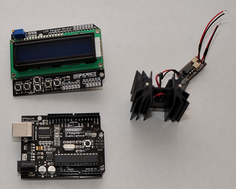
HiThe pieces:
10x10mm TEC mounted on a TO220 heatsink and connected to a LM358 Amp circuit per this thread:
DIY Thermal LPM for under $50
Aduino Board:
DFRobot DFRduino USB Microcontroller (ATMega168) - RobotShop
DFRobot LCD/Keypad Shield:
DFRobot LCD Keypad Shield for Arduino - RobotShop
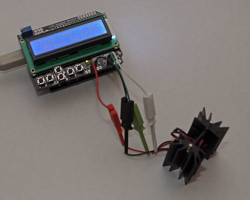
Assembly:
Amp Out+ => Arduino Analog input Pin1
Amp Out- => Arduino Analog input Pin2
Amp PWR+ => Arduino +5V Pin
Amp GND => Arduino GND Pin
Assembled with my sketch running:
The Analog input has only 10bit resolution for 0-5V, this means roughly 5mV per bit, which is not great but good enough for me. I could use the internal reference voltage and get about a 2mV per bit resolution, but this makes the keypad unusable since it uses Analog Pin0 assuming a 5V Vref. I am going to try redefining the keypad trigger values for the internal Vref at a later date.
The Select button starts the LPM sampling. Left starts dumping the LPM reading every second over the serial port so I can capture it in a terminal app to create a log. Right stops the data dump. Up resets the Max to zero and Down stops the LPM sampling. Reset is just a relocation of the reset on the Arduino board for convenience.
Here is a video of it in action. I still need to calibrate the amp as I don't have any metered lasers or calibrated LPMs.
Hi
Is this lpm software open source ? , i have both the shield and arduino and tec interface.. would like to test this.
thanks
I have already included the link in my previous post for arduino with lcdI mean the arduino project for the laser power meter using the lcd shield. does it have a specific name ? i found the delta isis and openlpm projects but not the lcd versions.