LPF Donation via Stripe | LPF Donation - Other Methods
Links below open in new window
ArcticMyst Security by Avery


You are using an out of date browser. It may not display this or other websites correctly.
You should upgrade or use an alternative browser.
You should upgrade or use an alternative browser.
Did I screw my driver??
- Thread starter amkdeath
- Start date


Benm
0
- Joined
- Aug 16, 2007
- Messages
- 7,896
- Points
- 113
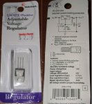
$2.29.. thats a major rip off ") Oh well, you get a retail package round it.
Oh well, you get a retail package round it.
Don't use ordinary 5mm leds as dummy loads.. as pointed out before, you'll blow them long before reaching regulation. Get something like a 1 watt luxeon star led if you want to use a led for a dummy.
Oh well, you get a retail package round it. Don't use ordinary 5mm leds as dummy loads.. as pointed out before, you'll blow them long before reaching regulation. Get something like a 1 watt luxeon star led if you want to use a led for a dummy.
Gazoo
0
- Joined
- Jun 9, 2007
- Messages
- 3,206
- Points
- 38
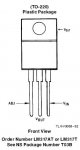
Grey Fox,
Thank you so much for posting the picture. Since amkdeath claimed on his Radio Shack package the middle pin was the adjust, it had me confused as to why the Radio Shack 317 would not be following the standard. Thanks to you there is no more confusion. The labeling of the pins on the RS 317 conforms to every single spec sheet I have seen. Thanks again
The following is from National Semiconductor's spec sheet:
Attachments
amkdeath
0
- Joined
- Oct 28, 2007
- Messages
- 2,631
- Points
- 48
Gazoo said:Grey Fox,
Thank you so much for posting the picture. Since amkdeath claimed on his Radio Shack package the middle pin was the adjust, it had me confused as to why the Radio Shack 317 would not be following the standard. Thanks to you there is no more confusion. The labeling of the pins on the RS 317 conforms to every single spec sheet I have seen. Thanks again
The following is from National Semiconductor's spec sheet:
hmm, I donno if you are saying I lied, or I am mistaken, although both statements would be incorrect.
I am looking at my regulator now, and it says pin 2 is ADJ
AND!!!
NOTE NOTE NOTE
!!!
My regulator looks different from that... the heatsink thing is a perfect square, not chopped off corners, also my regulator is bigger.
here is the pic from the radio shack website where I got mine:

I have 1 big LED that doesnt burn out when I attach it, and multiple regular ones that sizzle and fry when attached to driver. Should I attach the big one + 2 little ones? and one more thing:
Can I hook up my diode right now? will the driver work? will I mess up my LD?
Thanks for all your help
amk
No problem. RadioShack doesn't make their own chips, thankfully. They buy bulk and sell high. Things may be overpriced, but at least they have them when you need to get something together on short notice.Gazoo said:Grey Fox,
Thank you so much for posting the picture. Since amkdeath claimed on his Radio Shack package the middle pin was the adjust, it had me confused as to why the Radio Shack 317 would not be following the standard. Thanks to you there is no more confusion. The labeling of the pins on the RS 317 conforms to every single spec sheet I have seen. Thanks again
The pic you provided looks like the back of the 317s we all have. The clipped corners don't matter. It's the same package type, and some batches may have minor cosmetic differences. If you look at the reference schematic on the back of the package, it does look like pin 2 is adjust. This is not correct, and it does not mark the numbers for the pins. It's easy to become confused from that picture alone. Please also keep in mind that the schematic on the package is for a voltage regulator. To regulate current, you should use the schematic posted here by Daedal or any of the other variants for it.amkdeath said:hmm, I donno if you are saying I lied, or I am mistaken, although both statements would be incorrect.
I am looking at my regulator now, and it says pin 2 is ADJ
AND!!!
NOTE NOTE NOTE
!!!
My regulator looks different from that... the heatsink thing is a perfect square, not chopped off corners, also my regulator is bigger.
That said, the pinout for the chip is marked on the package as well. If you received an open/torn/damaged package, this additional information may have been missing.
amkdeath said:I have 1 big LED that doesnt burn out when I attach it, and multiple regular ones that sizzle and fry when attached to driver. Should I attach the big one + 2 little ones? and one more thing:
Can I hook up my diode right now? will the driver work? will I mess up my LD?
Thanks for all your help
amk
Simple answer, No. Don't hook up your diode yet. If you received faulty information on the chip pinout, it could seriously affect the regulator's operation.
As far as the physical size of an LED, it doesn't make much difference in the current draw. The smaller ones may have burned out faster because they operate with the same current on a lower voltage. Either way, it's a side point. A single, standard LED does not have enough current draw to allow this chip to function properly in the suggested current regulator circuit. If you must use an LED as a load, you need something more suitable. A 1W Luxeon was mentioned. These and similar can be found in many flashlights, and they are sold as 1W LED flashlights. A 1W LED exhibits (usually) similar characteristics to one of the group buy laser diodes and also many 16X DVD burner laser diodes. It makes a good test load for your supply. If you can't find one, you can use your current LED side by side with a 20 ohm 5W wirewound resistor. RadioShack sells these.
Gazoo
0
- Joined
- Jun 9, 2007
- Messages
- 3,206
- Points
- 38
amkdeath said:[quote author=Gazoo link=1193786909/15#18 date=1194224837]
hmm, I donno if you are saying I lied, or I am mistaken, although both statements would be incorrect.
I am looking at my regulator now, and it says pin 2 is ADJ
AND!!!
NOTE NOTE NOTE
!!!
My regulator looks different from that... the heatsink thing is a perfect square, not chopped off corners, also my regulator is bigger.
amk
Amk,
I wasn't accusing you of lying or being mistaken. What you have is either strange, or the package was mislabeled. I am more curious than anything else.
Can you post the exact numbers on the 317, if there are any? And BTW, the shape of the heatsink has nothing to do with identifying what you have.
amkdeath
0
- Joined
- Oct 28, 2007
- Messages
- 2,631
- Points
- 48
PROBLEM SOLVED
Sorry for ant misconception, or If I offended anybody, you were all a big help
2 things:
1st solution: more load
I hooked up a DC motor to the end instead of an LED, (BIG load difference, i hooked a big motor) and I got the pot working and all was well
2nd Solution: More input voltage
I hooked up more batteries (i had only 4 hooked up) and The pot was working, I was getting 3 volts instead of 5.something the pot could take it from 3 volts all the way down to 1.9 volts.
Thank you Gazoo, fox, and everybody else who contributed.
one last question... can I hook up my diode now?
THANK YOU VERY VERY MUCH
sorry for any confusion
please forgive me for any offence
amk
amkdeath
0
- Joined
- Oct 28, 2007
- Messages
- 2,631
- Points
- 48
thank you grey fox, now I cant wait untill my diode arrives from SenKat....
;D
;D
Personally, I'd run one more check. Connect an ammeter in series with your motor load and adjust the pot. See what kind of current range you get. You should have from around 50mA up to 300mA+. If you do indeed have this range, you're ready to go. A few things I always do to protect equipment:
Disconnect the regulator's input supply.
* The current regulator has a tendency to send a spike if it is powered up before a load is connected.
By powering it down before connecting the load, you reduce the likelihood that this will happen.
Connect an ammeter in series with the laser module.
Check the optics (laser lens, etc) and heatsink after connecting the laser diode/module to the power supply.
Lower the current to beneath the eventual operating current.
Turn it on and make the final adjustments under power, with focus adjustments done at minimum power.
and above all else: Stay safe and have fun!
Edit: Removed a mistaken mention thanks to the evening running along.
Benm
0
- Joined
- Aug 16, 2007
- Messages
- 7,896
- Points
- 113
The Grey Fox said:With 6V input, you should be able to see as much as 4.75V on the output. If you weren't getting that, you may want to check the connection where the power is taken for your load.
Not really, at least not when driving a load. You would lose at leat 1.25 volt in the reference, and also at least 1 volt in the actual regulator, and that's when the LM317 is performing better than specified (most do).
You should really just measure output current, preferably when driving a realistic load such as a power LED or a couple of diodes in series. But since this is a current source, you can even just hook an ampmeter to the output (shorting it) to check the value.
amkdeath
0
- Joined
- Oct 28, 2007
- Messages
- 2,631
- Points
- 48
sigh, It worked, I scavenged a diode from an old 50X CDRW/16XDVD burner thing. Burned like hell even without aixiz module or focusing. Took it out, soldered new wires and it still burned like hell. then I accidentally shorted the diode and now I have an LED...
ME SO SAD
oh well I guess Ill just have to wait for SenKat's diode to arrive.
ME SO SAD
oh well I guess Ill just have to wait for SenKat's diode to arrive.
Hiya I know im new but I have the same Lm 317 as Amkdeath its a LM317T the info i found on this one shows the Adj on the left pin when looking at the front
I got my info here circuit - innovations . co . uk / LM317 . html
I hooked it up going by that pic as mine was a bulk pack
works fine tried out a 1w lux LED star and i can adjust from sorta bright to blind the room bright
(sory wont let me post links yet )
I got my info here circuit - innovations . co . uk / LM317 . html
I hooked it up going by that pic as mine was a bulk pack
works fine tried out a 1w lux LED star and i can adjust from sorta bright to blind the room bright
(sory wont let me post links yet )
amkdeath
0
- Joined
- Oct 28, 2007
- Messages
- 2,631
- Points
- 48
Yea we got the problem fixed, turns out that I didnt have enough load, and that was causing my LM to just be lazy and do nothing. Preety good circuit, Can wait for my SenKat diode.......
