Howdy,
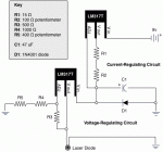
I'm trying to make a somewhat universal LD driver and this is what I came up with. It's based on Daedal's current-regulating driver, with an extra tidbit for voltage-regulation. I'm fairly new to electronics and the theory behind it, so if you don't mind using plain English...
The current is set using R2, which can be adjusted between 0 ohms and 100 ohms. Consequently, the final output current can be adjusted between (about) 10 mA to 90 mA (this is what I measured, not calculated...)
The voltage is set using R5, which can be adjusted between 0 ohms and 300 ohms. The final output voltage would then be between (about) 3.75 volts to 4.75 volts.
I was hoping I could get some input on the quality of this driver and what problems, if any, I would experience with it.
Main questions:
1. I feel like there should be more on the voltage-regulation part of the circuit. Schematics I've found for voltage-regulation with the LM317 include some capacitors around it, and I don't have any. As I said, I'm fairly new to electronics, so should I include a capacitor to avoid any spikes in the voltage coming from the LM317 on the voltage-regulation side of this circuit?
2. I've only tested this circuit using a multimeter to give me what the output voltage & current is with various settings for R2 & R5. I have not tried it with anything other than an LED. I keep reading that I need to try it under a load, but I don't know what this means. I've heard it suggested that I use 4 diodes in series to test it. How would this work? i.e. How do I know if it's working if plain black diodes are going to stay plain and black even if it is working?
Thanks a lot for any help!
Dave


