LPF Donation via Stripe | LPF Donation - Other Methods
Links below open in new window
ArcticMyst Security by Avery


You are using an out of date browser. It may not display this or other websites correctly.
You should upgrade or use an alternative browser.
You should upgrade or use an alternative browser.
Boost driver ideas...
- Thread starter GooeyGus
- Start date


- Joined
- Oct 25, 2007
- Messages
- 221
- Points
- 0
Shoot for about 25v for the electrolytics. I measured the volts at one of the caps at about 12v once. Ceramics are commonly 50v, which is fine.
All right,
I contacted my supplier and he sad that 10 uF smd ceramic capacitors did not exist. That the value was to high. And that he only had Tantalum and Electrolytic. Witch one is the best?
And about the scaling of the image of woop's circuit.
I tried to scale it down to 12%. I tried on two printers one normal printer and one laser printer. And they both where only able to go down to 25%.
So how did you scale your images down to 12%
Please let me know,
Thanks, Yoeri
:-? i am pretty sure they make them, cos i have some, and they measure around 10uF...jaap75 said:All right,
I contacted my supplier and he sad that 10 uF smd ceramic capacitors did not exist. That the value was to high. And that he only had Tantalum and Electrolytic. Witch one is the best?
And about the scaling of the image of woop's circuit.
I tried to scale it down to 12%. I tried on two printers one normal printer and one laser printer. And they both where only able to go down to 25%.
So how did you scale your images down to 12%
Please let me know,
Thanks, Yoeri
with the image scaling, when you press print, just type in 13% in the scale box under page setup
if you are using windows, open the image in paint, go to page setup and change the scaling to 13%, press ok and go to print.
Attachments
rkcstr
0
- Joined
- Dec 1, 2007
- Messages
- 1,368
- Points
- 0
jaap75 said:All right,
I contacted my supplier and he sad that 10 uF smd ceramic capacitors did not exist. That the value was to high. And that he only had Tantalum and Electrolytic. Witch one is the best?
Not sure what your supplier's saying... I have a few different 10uf ceramic caps rated 6.3V and 10V, 0805 sized, but you can get larger capacitance/voltage/size as well. Maybe they don't make them in whatever size or voltage you asked? :-?
jaap75 said:O.k I got the right scale. With my printer it was equally 15%.
About the capacitors, I guess he just doesn't have them.
But will Tantalum or Electrolytic work? 10uF is 10uF right?
That makes more sense. But, that depends on what the circuit needs... ceramics have very low ESR, which may be necessary in your circuit, in which case an electrolytic may not be good, but low ESR tantalums may work. It all depends on the circuit, which you shoudl read through the datasheet for suggestions.
the datasheet does specifically call for low ESR ceramics.rkcstr said:That makes more sense. But, that depends on what the circuit needs... ceramics have very low ESR, which may be necessary in your circuit, in which case an electrolytic may not be good, but low ESR tantalums may work. It all depends on the circuit, which you shoudl read through the datasheet for suggestions.
but tantalum's should work too, i used them on another similar driver with no problems
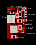
well i designed a board with high side current sensing using the lt6106. its 9 x 13.5mm
there is a bottom ground layer as well. thats where the green vias go
I haven't calculated resistances to set the current yet
my samples from linear came today so i can make it and test it out.
there is a bottom ground layer as well. thats where the green vias go
I haven't calculated resistances to set the current yet
my samples from linear came today so i can make it and test it out.
Attachments
rkcstr
0
- Joined
- Dec 1, 2007
- Messages
- 1,368
- Points
- 0
Awesome... looks good.
It should, my drivers are ~9.25x17.5mm and they fit... I think the inner dimensions of the module are ~10mmx20mm.
toked323 said:Very Nice woop, Does it still fit in an AixiZ module?
It should, my drivers are ~9.25x17.5mm and they fit... I think the inner dimensions of the module are ~10mmx20mm.
rkcstr
0
- Joined
- Dec 1, 2007
- Messages
- 1,368
- Points
- 0
toked323 said:Thanks rckstr.
Hey woop, Does linear really send one of their representatives to deliver a product?
Haha, I doubt it. I ordered a couple of samples for their opamp for the DIY power meter, they didn't even tell me I was approved or that they were sending them, just had an envelope in the mail a week or two later.
- Joined
- Jul 7, 2007
- Messages
- 492
- Points
- 0
hey i dont know if you guys know about this site but the person here designed a driver to run a blu-ray from just .4 volts. i will be getting one soon with a changed resistor to output 100ma for a phr-803t and will test it out. btw these things are absolutly tiny they are only .27" X .45"
http://images.google.com/imgres?img...nter&um=1&hl=en&rls=GFRB,GFRB:2007-50,GFRB:en
Thanks,
Mitch
http://images.google.com/imgres?img...nter&um=1&hl=en&rls=GFRB,GFRB:2007-50,GFRB:en
Thanks,
Mitch
