Welcome to Laser Pointer Forums - discuss green laser pointers, blue laser pointers, and all types of lasers

LPF Donation via Stripe | LPF Donation - Other Methods

Links below open in new window

ArcticMyst Security by Avery

Boost driver ideas...

Joined
Mar 8, 2008
Messages
2,669
Points
48
woop said:
[quote author=toked323 link=1212653254/24#24 date=1212807549]I think why drlava's is good is because he had to solder on the PD leg on a diode to the driver for feed back through the IC i think it cuts it off?  Best i think is to incorporate the PD leg into a design for feedback
i am pretty sure drlava's driver doesn't use the pd pin. it is just constant current like all the other drivers out there

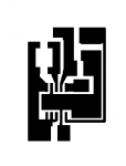
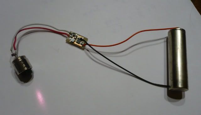
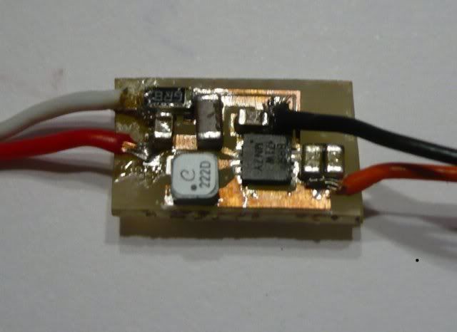
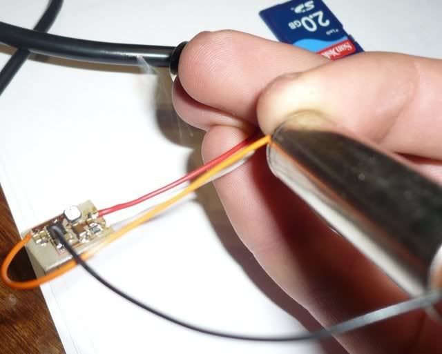
i made up a small board for this chip.
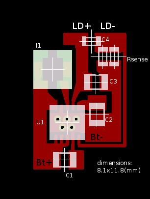
woop.png

u1= TI TPS61201,
I1= coilcraft LPS3015-222MLB,
C1-3= 10uH ceramic,
C4= low value ceramic,
Rsense= selected using R=0.5/I (where I is the required current).

this driver should not be used without a load.
and LD- must never be connected to Bt-.
power source can be a single AA cell.[/quote]

This is perfect... Almost exactly what I had in mind. Very few external components, etc etc. The only problem is that TI only makes these in qfn packages, making it a little more difficult for the average hobbyist to throw together. Also, what would it take to be able to use the battery ground? And finally, R = .5/I.... this may be an obvious question but I is in amps right? so 200mA would be R=.5/.2 correct?

great work!


woop

0
Joined
Nov 9, 2007
Messages
342
Points
0
yup I is in amps
to make LD- connected to Bt- it would require at least another chip and maybe some resistors.
basically it would be a clone of the lavadrive.
 
Joined
Mar 8, 2008
Messages
2,669
Points
48
woop said:
yup I is in amps
to make LD- connected to Bt- it would require at least another chip and maybe some resistors.
basically it would be a clone of the lavadrive.

Gotcha. I'm gunna try printing some of these up and see how they turn out. They should work great, especially since the stronger blu-ray diodes dont use a case ground so I dont really need to worry about making the LD- and the bt- common.
 

woop

0
Joined
Nov 9, 2007
Messages
342
Points
0
well here is a B+W printable version 600dpi
(printing at 12% gets the exact right size on my 600dpi laserjet)
size should be 8.1x11.7mm

and if you are doing the toner transfer method, invert the image before printing :p
i have ended up with quite a few useless boards because of not checking this
 

Attachments

  • printdriver.png
    printdriver.png
    493 bytes · Views: 238
Joined
Sep 1, 2007
Messages
1,591
Points
0
woop here is your image flipped
 

Attachments

  • printdriver_001.png
    printdriver_001.png
    454 bytes · Views: 168
Joined
Sep 1, 2007
Messages
1,591
Points
0
Heres a whole page for you too
 

Attachments

  • printdriver_001_001.png
    printdriver_001_001.png
    2.7 KB · Views: 232

woop

0
Joined
Nov 9, 2007
Messages
342
Points
0
thanks for that toked

i etched some boards today.
i used the 'direct toner transfer' method.
basically you print (using a laser printer) on to the non stick backing paper from stickers. and iron that to the boards. the toner sticks to the board and you can remove the paper.
then you put it in some etchant, because toner is water proof, it resists the etchant and you have copper tracks left under the toner.
(tip: rub off some of the waxy stuff from the non stick paper using a tissue to get the toner to stick to it in the printer, otherwise the toner gets smudged all over it)
here are some pics documenting the process
http://s197.photobucket.com/albums/aa189/yaywoop/pcb/
 

Attachments

  • P1020069.jpg
    P1020069.jpg
    92.1 KB · Views: 251
Joined
Sep 1, 2007
Messages
1,591
Points
0
woop said:
thanks for that toked

i etched some boards today.
i used the 'direct toner transfer' method.
basically you print (using a laser printer) on to the non stick backing paper from stickers. and iron that to the boards. the toner sticks to the board and you can remove the paper.
then you put it in some etchant, because toner is water proof, it resists the etchant and you have copper tracks left under the toner.
(tip: rub off some of the waxy stuff from the non stick paper using a tissue to get the toner to stick to it in the printer, otherwise the toner gets smudged all over it)
here are some pics documenting the process
http://s197.photobucket.com/albums/aa189/yaywoop/pcb/


when you say non-stick doesnt that meen you can use stadnard wax paper
 
Joined
Sep 1, 2007
Messages
1,591
Points
0
Very nice here are mine already flipped, Im pretty sure you can straight up print them out, Kudos to Rckstr for his help ;)
boostconvertPRINTcopy.jpg
 

woop

0
Joined
Nov 9, 2007
Messages
342
Points
0
wow crop or resize or something.
the first image is too low res to see whats going on, but there are lots of low res boards :p
and the second image is so huge LPF doesn't load it. 16490x21642 is WAY to big to be posting how did you even upload that?
is that double sided?
 

woop

0
Joined
Nov 9, 2007
Messages
342
Points
0
btw don't use jpeg for this sorta stuff. its really lossy and has artifacts. and png compresses solid lines better


and why did you post the layout with 121 boards on it? one would do for all intents and purposes

i mean seriously.. 20MB jpg!!! :-?
 
Joined
Mar 8, 2008
Messages
2,669
Points
48
Once again, great work on these. Now I just need to get a hot air station so I can get that qfn soldered on ;D

I've done it before with a full size heat gun... but its not the most delicate process ;D
 

woop

0
Joined
Nov 9, 2007
Messages
342
Points
0
I use a mini 'toaster' oven and smd solder paste
just put it in till the solder all melts.
 

woop

0
Joined
Nov 9, 2007
Messages
342
Points
0
toked323 said:
Very nice here are mine already flipped, Im pretty sure you can straight up print them out, Kudos to Rckstr for his help ;)

so did you design that layout?
it would probably be a good idea to have wide, short tracks. this circuit will be operating at 1.6Mhz and at high currents. looking at your design, it could cause to instability having such thin tracks.
it sorta looks more like a linear regulator design than a switching regulator :-/

also, why bother with double sided?

just trying to help you out
 
Joined
Mar 8, 2008
Messages
2,669
Points
48
woop said:
I use a mini 'toaster' oven and smd solder paste
just put it in till the solder all melts.

Where do you get your solder paste? In theory, could one just set it with the paste, make sure its held down so it wont float around, and then use a heat gun to melt it?
 

woop

0
Joined
Nov 9, 2007
Messages
342
Points
0
i got it from jaycar (australia). pretty expensive stuff but 60g of it will last a long time.

I put it all together. testing with a 2.2V 147mA IR laser diode using a 1.2V AA battery it drew 420mA. thats 61% efficiency
this is expected with such a low voltage diode. 19% is lost in the sense resistor.
the efficiency should be above 75% with a violet and probably around 65% for a blue burner.

not too bad for a driver that fits inside an aixiz module and runs off one AA

overview.jpg

closeup.jpg

burning.jpg


Top