Welcome to Laser Pointer Forums - discuss green laser pointers, blue laser pointers, and all types of lasers

LPF Donation via Stripe | LPF Donation - Other Methods

Links below open in new window

ArcticMyst Security by Avery

Blanking DDL

Joined
Jan 12, 2008
Messages
3,290
Points
83
I want to make some sort of blanking for my RGV. What if I put a transistor across the laser diode so the current goes thought the transistor when I want to turn the beam off? Would this work for PWM? Is there any risk for spiking?
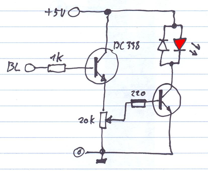
ttl-1.jpg


Joined
May 24, 2007
Messages
283
Points
0
i would not do it like that

u have to put the transistor in series with the diode  to use blanking
else u are shorting the diode with the transistor causing possible spikes in drive output and killing the diode
small example


1z32naf.png
 

Benm

0
Joined
Aug 16, 2007
Messages
7,896
Points
113
Well, if your driver is a true and good current source, just shorting it out with a transistor should work fine (albeit inefficient). I'm not all that sure the LM317 will handle it well though, it was never intended for this purpose and the rapid switching could throw it off.

As for the schematic above: It looks good on paper, but have you actually tested it? My experiences with operating the TL082 inputs so close to the ground rail aren't good at all. I've build similar contraptions using a CA3140 as the opamp, which works very well near the ground rail, as long as its supply voltage is good (>5 volts, should be okay with 2 lith cells).

Also, it will not fully blank as you've drawn it there, the CE voltage at saturation is still a few 100 mV for the BC548. Resulting current will likely be below lasing treshold, but its not completely off.
 
Joined
Jan 12, 2008
Messages
3,290
Points
83
Damn that looks complicated. I don't want to experiment, it's a real pain without a bread board. Will it work with a CA3140 opamp instead at 5V? What diode is D1?
 
Joined
May 24, 2007
Messages
283
Points
0
Benm said:
Well, if your driver is a true and good current source, just shorting it out with a transistor should work fine (albeit inefficient). I'm not all that sure the LM317 will handle it well though, it was never intended for this purpose and the rapid switching could throw it off.

As for the schematic above: It looks good on paper, but have you actually tested it? My experiences with operating the TL082 inputs so close to the ground rail aren't good at all. I've build similar contraptions using a CA3140 as the opamp, which works very well near the ground rail, as long as its supply voltage is good (>5 volts, should be okay with 2 lith cells).

Also, it will not fully blank as you've drawn it there, the CE voltage at saturation is still a few 100 mV for the BC548. Resulting current will likely be below lasing treshold, but its not completely off.

Hi ben i totaly agree with u a decent driver should not have any problems with the transistor shorting the driver / diode

ive not used the schematic below.
but have used a lm317 with a transistor in series to blank the laser.
and havent had any problems with it
it handeld blanking speeds up to 10 khz without any problems
the picture ive posted was only a reference on how to place the transistor in series with the diode.
i havent used the actual schematic
 
Joined
May 24, 2007
Messages
283
Points
0
FireMyLaser said:
Damn that looks complicated. I don't want to experiment, it's a real pain without a bread board. Will it work with a CA3140 opamp instead at 5V? What diode is D1?

u dont realy need the entire schematic
just make a basic lm317 driver and put the transistor in series with the diode.
ill try to post the correct schematic later when im back home
im currently at work lol
 
Joined
May 24, 2007
Messages
283
Points
0
Small other example

Just connect your lm317 drivers output to the positive and negative and your set

scannen0006.jpg
 

Benm

0
Joined
Aug 16, 2007
Messages
7,896
Points
113
That last schematic will not work...switched at the wrong point ;)
 
Joined
Jan 6, 2009
Messages
202
Points
0
Note that it is highly suggested that even in the "off" state of the TTL modulation that the diode gets enough current to stay above the lasing threshold.  Diodes don't like being turned on and off repeatedly but if you stick a resistor in parallel with the transistor to ensure there is always 20-30mA going through the diode.

If you just want an easy circuit and are not concerned about the frequency of modulation, almost any driver can take 500Hz-1000KHz. I just attached the modules to my arduino for the beam combiner in my signature.
 
Joined
Jan 12, 2008
Messages
3,290
Points
83
I do want an easy circuit.
It has to be with the diode hooked to ground and lets say a 5V TTL signal. Please post working schematic and which components needed. I've tried a few different ways with the lm317 earlier but the caps screw everything up. :-/
 

Benm

0
Joined
Aug 16, 2007
Messages
7,896
Points
113
Output capacitors over the LD will mess with PWM or blanking if they are too large, there is no way to remedy that but to reduce the capacitors, or accept the slower response.

The schematic posted by laserfreak3d will work, but i would suggest using a CA3140 opamp instead of the TL082.
 
Joined
Jan 12, 2008
Messages
3,290
Points
83
But the diode is not connected to ground. The red and violet diode is common negative to the chassis.
 
Joined
Jan 6, 2009
Messages
202
Points
0
I just attached a rkcstr driver and the driver that comes on o-likes green modules straight through a transistor.  Both drivers could take the arduino's  default 522Hz PWM with no problem, the rkcstr can go significantly faster.  I wouldn't try this with a flexdrive though.

If I did it again I would use something like this.  Note that all the symbols are probably wrong and this circuit wont work (When I do electronics I have to look every second thing up):
50857730.jpg

Basically stick a transistor and resistor in parallel in front/behind the regular driver.

The resistor would be chosen to allow 30-40mA of current through no matter what to keep the diode above lasing threshold.

The capacitors start messing with the PWM if you go above a KHz or two but otherwise you are fine.
 

Benm

0
Joined
Aug 16, 2007
Messages
7,896
Points
113
I suppose that setup might work, but it is active-high, i.e. you need to put positive supply on the transistor base to turn the laser on. Not sure about the resistor though, but if you can make the driver pass some current out of regulator to maintain lasing just above treshold, it could work.

A BUX86 is a high voltage transistor with a big voltage drop from collector to emitter. I'd suggest a standard small signal NPN like BC337. Emitter should be on the right in the schematic drawn above.


Top