Welcome to Laser Pointer Forums - discuss green laser pointers, blue laser pointers, and all types of lasers

LPF Donation via Stripe | LPF Donation - Other Methods

Links below open in new window

ArcticMyst Security by Avery

APL1117 Regulator?

Joined
Jan 20, 2008
Messages
1,724
Points
0
Here is the third installment of the ongoing saga of my failures at interpreting circuit diagrams and other completely basic things...

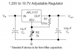
Anyways, today I decided to try making a driver out of whatever parts I had laying around... I found this regulator in an old laptop and a few cdrom drives I had... It says it handles up to an amp and has a low dropout voltage, so I thought it could work out well... After a few false starts I've built the circuit laid out in the reference schematic I found in the datasheet and it seems to work the way it should... I did have a couple problems though...

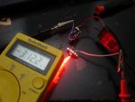
I used a couple LEDs as a dummy load and found 175-200ohms across the pot lets the LEDs draw 275-350mA, so I set it around there and put in one of my useless rectangular 16x diodes... When it's first turned on it draws around 400mA for about a second, then drops to around 290... then if you let it sit, the current slowly drops till it reaches about 160mA and settles out. Interestingly, I didn't notice a real drop in light output...

I figured this was probably something thermal, so I soldered a penny onto the laser, and another onto the regulator to sink the heat... Sure enough the current became much more stable and stayed around 300mA. After about 5 min of running I checked the pennies for heat buildup and the diode had barely made the penny warm at all, whereas the regulator's penny was scorching hot and my skin sizzled when I touched it.

These regulators are supposed to be rated up to 1A, so why is it getting so unbelievably hot at 300mA?
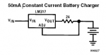
Is there a fundamental difference between this voltage regulator, and say, a lm317t (presumably a current regulator of some sort)??
 

Attachments

  • DSC00445.JPG
    DSC00445.JPG
    64.1 KB · Views: 2,141


phenol

0
Joined
Oct 30, 2007
Messages
533
Points
18
these regulators come in fixed voltage (1.8,2.5....) and adj voltage versions. Hopefully you have the latter.
An important thing about them is that their controlled output device is a PNP transistor and the load is connected to its collector; the output impedance is higher compared to LM317, which sports NPN output stage where loads are connected to its emitter.
In practical terms this means that 1117 is potentially unstable without high quality low ESR bypass capactors (10uF min, tantalums). I messed with one a little while ago (in a constnct current configuration) and oscillations ceased only after i bypassed all pins with caps to ground.
 

woop

0
Joined
Nov 9, 2007
Messages
342
Points
0
i reckon the current is probably drifting as the led heats up. because you have it set as constant voltage right?
you should set it up as constant current, it should be exactly the same as using an lm317 as a constant current source (i think)
what input voltage have you got running it? and what voltage is the led at? the regulator probably has to drop a lot of voltage, and a lot of power which turns into heat
 
Joined
Jan 20, 2008
Messages
1,724
Points
0
phenol: yeah, the one's I've found seem to be variable... I'm guessing the fixed voltage ones would have different numbers after the part number... I'm not too sure what to think about oscillations and I don't have a scope to find out if they'll pose a problem... the caps I'm using are probably cheap, electrolytic ones I've salvaged. Assuming I'd be driving this 50mA inside the safe zone do you think any spurious current would pose a problem?

woop: yeah, on the bus I was thinking about that... it's probably the voltage I'm using - a 12v power supply, which seems to only put out 8.8 to 9.2v. Checking the data sheet it seems 12v is the max you should give it... I'll probably use a much lower voltage in the finished product. Seeing as it has "On-Chip Thermal Limiting : 150[ch8451] Typ." I'm guessing it's meant to be able to take that kind of ridiculous heat.

Anyways, could someone explain to me the difference between running a regulator like this in "constant current mode" and just building the variable voltage reference design shown in the datasheet? I've heard that term a few times here and I'm not sure I understand what people mean by that... I didn't see much of a difference between this and daedal's circuit, I figured it should accomplish more or less the same thing.
 

phenol

0
Joined
Oct 30, 2007
Messages
533
Points
18
o well, this is a constant voltage source. Vout can be adjusted via R2. No wonder it got sizzling hot - if you fed diodes with it, it tried to keep the output voltage constant and the current needed for that heated it up. It does have thermal shutdown, but normally such precautions are intended as a short-term protection. dont keep it running for long under such marginal conditions.
In a little while I'l post the schematic that worked ok for me.
 

woop

0
Joined
Nov 9, 2007
Messages
342
Points
0
basically that regulator works by changing the 'out' pin untill there is 1.25v between the out and adj pins.
so for constant voltage mode it uses a voltage divider to divide the output voltage to get 1.25v between the out and adj pins. so its constant voltage.

for constant current, you use what is called a shunt to convert the current into a voltage (ohms law I=V/R) a shunt is just a resistor,
take a look at the lm317t data sheet and look at the application hints for the constant current source. it should be the same for the 1117.
http://cache.national.com/ds/LM/LM117.pdf

by the way, the name 'low dropout' can be a bit miss leading when you use a regulator to regulate current. because the voltage you will need to run it will be the dropout voltage (1.3V) plus the shunt voltage (1.25V) plus the output voltage (the voltage across the laser)
 

phenol

0
Joined
Oct 30, 2007
Messages
533
Points
18
Without C2 my circuit would oscillate at about 4MHz. C1 and C2 should at best be tantalum or ceramic with low esr for high frequencies. C3 could be any value greater than 10uF, electrolytics would also do there
 

Attachments

  • l1117.JPG
    l1117.JPG
    16.8 KB · Views: 4,628
Joined
Jan 20, 2008
Messages
1,724
Points
0
Hmm... well I guess I have some gaps to fill in my knowledge.. I basically taught myself everything I know, so a lot of it I make up as I go along...

So by a "shunt" do you mean like a resistor going from V[sub]out[/sub] to GND? I know of ohm's law and I was aware that diodes offer little internal resistance (basically a short), but I thought R1 was acting as a shunt in this example. I'm still not sure I understand what's meant by "constant current mode"... every example I've seen so far simply puts a resistor between V[sub]out[/sub] and ADJ
 

Attachments

  • untitled2.PNG
    untitled2.PNG
    5.1 KB · Views: 927

phenol

0
Joined
Oct 30, 2007
Messages
533
Points
18
in the cc mode the regulator feeds the load with a preset current, which depends on the resistor between adj and Vout pins. For LM317 and ur chip the current is calculated as follows: Iout=1.25/R. The voltage on the load depends on the load itself. If ur load is a resistor, the voltage=IxRLoad. If your load is an LD - the voltage depends on its junction properties.
In The constant voltage mode  the regulator maintains constant voltage on its output. The current depends on the load - in the case of a resistive load, it can be predicted using ohm's law. In the case of a non-linear load, such as a diode, things get complicated --a small change of diode's properties (due to temperature fuctuations) could result in big variation of the current that flows thru it. In some cases the output power would drop, in others - the diode would burn due to excessive current...anyway, this topic has been broadly covered in other threads. Keeping the long story short - use the constant current configuration to power LDs The electrical parameter we use to describe their working condition is above all current. At a fixed current we could measure the voltage across the diode. It is also important when designing drivers, but it is a dependable variable we have to take into account. The target variable is current.
 

IgorT

0
Joined
Oct 24, 2007
Messages
4,177
Points
0
pseudolobster said:
I'm still not sure I understand what's meant by "constant current mode"... every example I've seen so far simply puts a resistor between V[sub]out[/sub] and ADJ

There is a shunt (resistor) between Vout and Adj, but look at how it is put between them. In your example, the shunt goes to GND, in Phenol's 317 example it is in series with the load (goes to the load).

Constant current means, the regulator will keep adjusting the voltage all the time, in a way, that it always gives the load just enough voltage, for the current to stay the same.

With constant voltage on a diode, the current will change a lot (climb) with heat, but with constant current, the voltage will change a little with heat (drop), so the current can stay the same, even when the internal resistance of the diode drops from heating up.


With constant current, you can push a diode further, and safer at the same time.


Top