Welcome to Laser Pointer Forums - discuss green laser pointers, blue laser pointers, and all types of lasers

LPF Donation via Stripe | LPF Donation - Other Methods

Links below open in new window

ArcticMyst Security by Avery

analog LD driver??

3zuli

0
Joined
May 30, 2009
Messages
810
Points
28
does anyone have schematic of analog modulated LD driver?
or anz ideas how to make one?

yes, I used the SERACH button
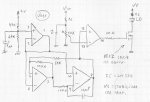


HIMNL9

0
Joined
May 26, 2009
Messages
5,318
Points
0
Not handy, but i suppose it can be drawed ..... what's the driving voltage and polarity, and what you're searching exactly ?

I mean, sorry .....

Input driving voltage ? from Vmin to Vmax ? ..... like, from 0 to 10, or what ?

Positive o negative respect the ground ? (0 to +V or 0 to -V ?)

Type of modulation ? (means, "0v=off > Vmax=on", or "0V=on > Vmax=off" ?

Going to sleep now, but maybe can look for something, tomorrow, if i know these data (still not promising anything, depend how much time i have at work :D)
 

3zuli

0
Joined
May 30, 2009
Messages
810
Points
28
I mean Vin <10V, positive respect to gnd and 0V=off, full V=on

just post any ideas...
 

HIMNL9

0
Joined
May 26, 2009
Messages
5,318
Points
0
Sorry for the delay, but i had not too much time today, cause work.

Anyway ..... starting with something simple, without search custom ICs, it can be done, i think, in this way .....

attachment.php


It's a very old application of the LM324, a variable-cycle PWM oscillator, where the variation of the duty-cycle is obtained with a fixed-rate sawtooth wave (the two op-amps in oscillator configuration) and a comparator that change its state in report from the level of the sawtooth and the input level ..... the last op-amp is just a 6V reference generator ..... if a different Vref is used, that can give half of the Vsupply, the op-amp can be used for condition the input signal, or just can be added an LM741 if is needed for balance the impedences (i don't have at the moment any DAC card, so cannot made experiments about the impedences, sorry)

In case the level of the input is too low for turn on the output at the low Vin (mean, if you have to rise the Vin too much for start to have an output), a second 10K trimmer can be added between the first and the ground, for change the input curve (but i still think that an op-amp can work better)

The circuit is not a personal invention, i use it from 15 or 20 years, time by time, and i don't recall exactly from where it come ..... there was a kit, a lot of time ago, that was using something similar to this circuit for drive a motor (but from a potentiometer, not with an external input), and i also think i took the basic of this schematic from a very old datasheet, but don't know exactly from where.

Anyway, it's a starting point, and can be changed for adapt it to our specific use ..... just, it probably need to have a different power source for the LD, cause you cannot modulate and at the same time keep the current constant ..... the better way can be to use a stable voltage regulator (NOT a current regulator, a voltage regulator), and set it for the voltage that give you the wanted maximum current through the LD, with, as example, an RI of 10 ohm 3W (or 5W) resistor in serie (that can also be used for measure that current during the setup :p), when the modulation is fully ON (the maximum Vin level) for the VS power point ..... so, any other level of Vin will be inside the wanted working range of the LD ..... and use a different stabilized 12V power supply for the rest of the circuit (V+ power point, and the power of the IC ofcourse :p)

Had no time for tests, but in the next days can made some one ..... in the meantime, if someother want to do some other test, let me know, thanks (more peoples made tests, more data we have at the end, after all)
 

Attachments

  • analog-pwm-mod-1.jpg
    analog-pwm-mod-1.jpg
    98.7 KB · Views: 9,800


Top