Welcome to Laser Pointer Forums - discuss green laser pointers, blue laser pointers, and all types of lasers

LPF Donation via Stripe | LPF Donation - Other Methods

Links below open in new window

ArcticMyst Security by Avery

2 AAA Ni-MH or 1 Li-Po adjustable LASER driver

IgorT

0
Joined
Oct 24, 2007
Messages
4,177
Points
0
When I was building my first laser, I bought a very small, good looking enclosure for it. Unfortunately, that meant I didn't have enough place for 6 Ni-MH batteries, to use the LM317 driver, so I had to leave current regulation out of the equation...

Since the internal resistance of the LD drops, as it heats up, this means the current will go up, if voltage stays the same. A driver would drop the voltage a little in this case, but I didn't have this luxury. So to keep my laser safe, I had to set the current lower, than I could with a real driver. This way, as it would heat up, the current still wouldn't increase over the maximum.

But this isn't the only drawback of "direct drive". As the battery discharges, it drops in voltage, so the output power is smaller, every time I power it on.


But I want my lasers small and powerful at the same time. So I decided to try with a boost circuit, which can turn a low voltage into a higher one. We discussed this in another thread: http://www.laserpointerforums.com/forums/YaBB.pl?num=1194375801/0

I tried a MAX765 and a MAX1674 circuit, which can make between 3 and 5.5V out of only one or two Ni-MH cells.


After testing these ICs, the results were very discouraging. The efficiency was very low, and the output wasn't constant at all. Besides, they can't regulate the current.


Then Woop mentioned a special SEPIC converter, which can regulate the current from a voltage higher or lower, than the output, the LM3410. Datasheet here: http://cache.national.com/ds/LM/LM3410.pdf - Design example 6

Several of us made our own PCBs and built this circuit, and I finally got the results I was waiting for!


This circuit can regulate the current from an input voltage between 2.7 – 5.5V, which makes it perfect for driving a laser from only one Li-Po cells, or even two Ni-MH cells with a simple modification. The current is adjustable with a resistor and the same circuit could be used to power any laser diode.. For low currents, the resistor could even be replaced with a trim pot. (blue ray readers)


I got an efficiency between 70 and 74.5%, which is almost twice the efficiency of the LM317 and means, that the laser would work from one Li-Po around 72% as long, as it would from two with the 317! With two Ni-MHs it would still work for around 70% as long as it would with six Ni-MHs on the 317.
The efficiency could get better with a professionally designed PCB and better components, but I am very happy with it, as it is.


I tested it on several different laser diodes and other loads and it works great. There were some concerns about current ripple, but with some advice from Phenol I managed to get the ripple so low, that it was hardly measurable, when I tested it with my electronics engineer today.

I'm gonna use this circuit with all my future lasers, and now that I got AAA size Li-Pos from DX, I can finally convert my poor "direct drive" laser to current regulation in that same tiny enclosure.


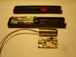
I had an old laser pointer (my first laser ever) that took two AAA cells, and had less than 1mW of power. It was dead for 8 years now. But this circuit allowed me to revive it, and at almost 200 times as much power!


Here's the picture of the old pointer with the new circuit next to the AixiZ module...
 

Attachments

  • Old_pointer_revival.jpg
    Old_pointer_revival.jpg
    25.3 KB · Views: 554


IgorT

0
Joined
Oct 24, 2007
Messages
4,177
Points
0
This is a picture of the laser assembled together..

The momentary push button was glued in, and a slide switch put next to it.. I don't like momentary buttons and too much on/off cycling.


The AixiZ module is a little smaller in this picture, since i had to cut some of it away to make it fit.. But i didn't want to discard it completelly, since it provides some additional heat sinking and protects the LD's connections with the tiny SMD capacitors across the leads.
 

Attachments

  • Inside.JPG
    Inside.JPG
    24.5 KB · Views: 784

IgorT

0
Joined
Oct 24, 2007
Messages
4,177
Points
0
And the two lasers side to side.. The one on the left is still direct drive, but it gets upgraded today.


EDIT: I found, the pointer i used in this conversion is still being sold today, but as a 5mW DIY kit, at this link:http://www.lasermate.com/DIY.HTM When i bought it, it was much more expensive and below 1mW..

Too bad, they don't sell only enclosures..
 

Attachments

  • Old_and_new_3.JPG
    Old_and_new_3.JPG
    206.1 KB · Views: 287

IgorT

0
Joined
Oct 24, 2007
Messages
4,177
Points
0
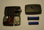
And this are the insides of the laser i am converting right now..

Next to it is the assembled enclosure i am using and the tiny AAA size Li-Pos from DX.. Only one of these will be enough to power the laser with current regulation.


The enclosure is meant for door opener remotes and has a button included. I like it very much, because it's  very small (74x44x18mm) and has a nice shape.


I'm gonna use the same driver for the open can, but the enclosure will be different, since it will also have to house a tiny peltier cooling system. It will also have a larger Li-Po of course...
 

Attachments

  • Direct_drive_laser.JPG
    Direct_drive_laser.JPG
    34.8 KB · Views: 369

IgorT

0
Joined
Oct 24, 2007
Messages
4,177
Points
0
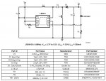
This is the schematic of the driver and the list of components..

I found all the required capacitors and resistors in old DVD drives.. The ICs were ordered as samples from National Semiconductor, and the inductors from CoilCraft and the substitute diode i used is a 1N5817..


Additionally i put two 47uF tantalums on the circuit output for the power on spike, and some small ceramic 1uF SMD capacitors directly across the leads of the LD, for high frequency current ripple supression.


For even better filtering, two axial chokes could be put between the circuit output and the LD, one on the positive and the other on negative output, but it seems they are not necessary.. Still, i'm probably gonna use them for the Blue Rays, since they are more sensitive. When chokes are used, they make the ripple so small, that it is hard to measure.


The only drawback of this circuit is, that the LD minus pole is not at the GND potential. If a flashlight was used as a host, the LD module would have to be isolated from it. Since i'm using plastic enclosures, it doesn't matter, but Phenol made a version, where the negative LD lead is at the GND potential, at the cost of an additional IC.


There are several different PCB pictures available on the DC/DC converter thread. They are very easy to etch, using toner transfer method from label backing paper, and the only component that is hard to solder is the IC.. The rest is a piece of cake.
 

Attachments

  • Circuit_and_component_list.jpg
    Circuit_and_component_list.jpg
    115.6 KB · Views: 2,209

woop

0
Joined
Nov 9, 2007
Messages
342
Points
0
carefull of the ratings for capacitors used in this circuit. the tantalium cap i had on the input EXPLODED and started glowing red after a few minutes with a li-ion powering it.
 

IgorT

0
Joined
Oct 24, 2007
Messages
4,177
Points
0
woop said:
carefull of the ratings for capacitors used in this circuit. the tantalium cap i had on the input EXPLODED and started glowing red after a few minutes with a li-ion powering it.

Oh, right... You used a tantalum on the input.. I used all ceramics, and the biggest ones i could find. I only have two tantalums on the output, and again, they are bigger ones.


Did you try powering a laser from this yet?
 

woop

0
Joined
Nov 9, 2007
Messages
342
Points
0
I made a nice little li-ion powered led torch from one of the circuits.
i did buy another pioneer 115D, but the laser didn't survive extraction :(
i am sorta sick of lasers now
 

IgorT

0
Joined
Oct 24, 2007
Messages
4,177
Points
0
woop said:
I made a nice little li-ion powered led torch from one of the circuits.
i did buy another pioneer 115D, but the laser didn't survive extraction :(
i am sorta sick of lasers now

Too bad..


I'm having problems with my brand new DX200.. It would seem i got a very unstable one, and it looks like they have no regulation whatsoever..
I'm probably going to convert it to current regulation, and set it to a stable power. Maybe even use this circuit, if i put it in another host for improoved cooling...
 

woop

0
Joined
Nov 9, 2007
Messages
342
Points
0
w00t. i now have an open can from another 115d that did survive.
i will try it using my sepec board soon
 

IgorT

0
Joined
Oct 24, 2007
Messages
4,177
Points
0
woop said:
w00t. i now have an open can from another 115d that did survive.
i will try it using my sepec board soon

That's great!

I knew you wouldn't just get sick of lasers... :)
Post some pictures, when you're done!


You know what i was thinking of... I would like to make it double sided, so that it could be more narrow and "round", and fit into laser pens and other round hosts...

You think that could work? I mean, I know it could, I just don't know if I can do it. But I'll try.
 

woop

0
Joined
Nov 9, 2007
Messages
342
Points
0
ok i connected it and it works! its set at around 300mA, so i am not pushing it too hard i would expect the output is around 190mW. the noise from the smps plays havok with the TV :p
enough to be really bright, and light black powder

i need to find a 1/2ohm pot to make it adjustable
another option would be to use an opamp, which would have the bounus of allowing the laser case to be grounded, and let you use any switching chip, maybe one with a lower minimum input voltage
 

Attachments

  • lasersmps.JPG
    lasersmps.JPG
    81.8 KB · Views: 510

IgorT

0
Joined
Oct 24, 2007
Messages
4,177
Points
0
I'm not getting any noise or interference.. And my circuit works down to 2.2V without the bootstrap modification.. With it, i would imagine it would go even lower.. And now that i can get AA and AAA size Li-Pos for cheaper than same size alkalines (with similiar or higher energy density), i really don't care about the minimum voltage requirements.


Where are you going to get a 1/2 Ohm pot? Can they take these currents?

I'm happy with setting the current using resistors. I left some space, so i can put several in parallel and/or in series if needed, to get to the exact current i neeed.

Besides, i don't trust pots when pushing LDs to such high currents.. A dirty wiper could destroy the LD or even the IC if there is no Zener across the output in reverse.
 

IgorT

0
Joined
Oct 24, 2007
Messages
4,177
Points
0
BTW, that heatsink looks like it could be usefull.. It could easily be mounted on a peltier.

Where is the bent part joined? Do you have good contact? I want to do something similiar, but i will wrap the entire AixiZ module in it, for better thermal conductivity.
 

woop

0
Joined
Nov 9, 2007
Messages
342
Points
0
I haven't tested the voltage limits of this one yet. as for the pot, i don't know...

you like the heatsink? I made it today from a short piece of copper pipe i had. i used a dremel to accross the pipe 3/4 through and then cut that part of the tube open. i used pliers and a vice to flatten that section so it could be mounted on a heatsink or peltier
the aixis module happens to screw in quite tightly, i also used some thermal grease to better conduct. it can easily conduct the heat produced, copper is a much better conductor than the old brass casing.
its really hard to get it perfectly flat though. maybe a better way would be to buy a small copper plate and use solder (maybe silver solder) to connect a piece of tubing.

where are you getting the small lithium batts?
 

IgorT

0
Joined
Oct 24, 2007
Messages
4,177
Points
0
woop said:
you like the heatsink? I made it today from a short piece of copper pipe i had. i used a dremel to accross the pipe 3/4 through and then cut that part of the tube open. i used pliers and a vice to flatten that section so it could be mounted on a heatsink or peltier
Yeah, i like it..

But i was thinking the other way around.. I thought it was flat, and then you cut a bit, and bend it to form a circle.. That's why i asked, where the bent part is joined...

But if it started out as a tube, then the contact with the AixiZ module would be even better of course. I think it should be very usefull. Especially, if it just screws in...

I would imagine, it is hard to get it flat, but a vice should do the trick.. Or did you try it? It would have to be as flat as possible for best efficiency..


where are you getting the small lithium batts?
DealExtreme.. They are 10440 AAA size and 14500 AA size.

The 10440 have a stated capacity of 600mAh, but it's measured around 400, which brings them slightly above the energy density of the same size Ni-MHs..
The 14500 have a stated capacity of 900mAh, which would bring them to the same energy density as 2700mAh Ni-MHs of the same size, but since the actual capacity is probably lower, they contain a little less power.

Still, at these prices, i just don't care.. Quality Ni-MHs would cost me a lot more where i live. And a Li-Po gives the SEPIC the perfect range of voltages, even for very high currents and doesn't sag enough to lose regulation..


EDIT:
- UltraFire, unprotected 10440: http://www.dealextreme.com/details.dx/sku.974
- UltraFire, unprotected 14500: http://www.dealextreme.com/details.dx/sku.975
- TrustFire, protected 14500: http://www.dealextreme.com/details.dx/sku.3435


Top