Welcome to Laser Pointer Forums - discuss green laser pointers, blue laser pointers, and all types of lasers

Buy Site Supporter Role (remove some ads) | LPF Donations

Links below open in new window

FrozenGate by Avery

RGB Module Build 300mw+ single mode

Joined
Mar 5, 2015
Messages
1,333
Points
113
Hi

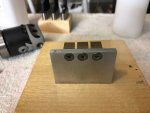
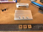
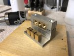
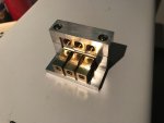
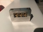
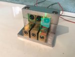
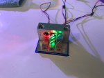
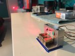
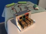
This was a lot of fun to build and surprisingly very easy to align due to the brass
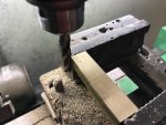
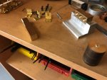
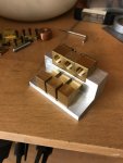
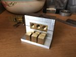
Mounts I made from a brass bar, very similar design to the opt lasers module mounts,

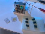
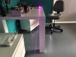
I tightened up my mounts straight and then UV glued the dicros while watching the beams on a wall 5 metres away to within a few inches, then all was left is apply a little pressure with a flathead in X or Y direction and bingo one beam.

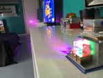
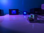
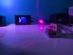
I might need a little adjustment of the Flexdrive pots to get a pure white beam, it looks a tiny bit violet as is, I used all 5.6mm single mode diodes.

PLT5 450B 120mw
PL520 50mw
ML520 G55 180mw

All 3 Flexdrives were set at the 100-400ma range so I have a good amount of room for adjustment.

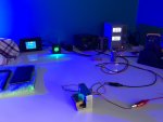
I LPMed the module at over 300mw but my LPM isn't the best for low power metering.

Glad I built the top aluminium cover as it gets nice and warm after a few minutes, it's very small and would very possibly go into a custom host later,
A lot of work but this can be done very cheap, $100 for diodes, $100 for Flexdrives and $40 for dicroic mirrors and a lot of work on the mill.

Now I can get to work on my custom 589 build, I'll let the pics do the rest,
Thanks for checking this out,

Pic heavy!

https://youtu.be/S9Nqp_kDEq4
https://youtu.be/uogZuVRo7-c
https://youtu.be/b5uv69KOsGU
https://youtu.be/nqql5o66EIY
 

Attachments

  • 1489978966.6445.jpg
    1489978966.6445.jpg
    318.2 KB · Views: 118
  • 1489979007.3916.jpg
    1489979007.3916.jpg
    354.4 KB · Views: 119
  • 1489979043.972.jpg
    1489979043.972.jpg
    189.3 KB · Views: 100
  • 1489979083.9023.jpg
    1489979083.9023.jpg
    289.3 KB · Views: 136
  • 1489979119.8552.jpg
    1489979119.8552.jpg
    266.3 KB · Views: 118
  • 1489979153.8689.jpg
    1489979153.8689.jpg
    376.7 KB · Views: 125
  • 1489979186.6619.jpg
    1489979186.6619.jpg
    326.4 KB · Views: 116
  • 1489979220.3567.jpg
    1489979220.3567.jpg
    243.1 KB · Views: 156
Last edited:
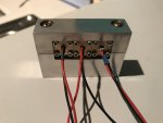


RGB module
 

Attachments

  • 1489979313.4123.jpg
    1489979313.4123.jpg
    209.8 KB · Views: 97
  • 1489979343.1578.jpg
    1489979343.1578.jpg
    238.3 KB · Views: 119
  • 1489979371.0534.jpg
    1489979371.0534.jpg
    261 KB · Views: 100
  • 1489979401.2505.jpg
    1489979401.2505.jpg
    316.8 KB · Views: 88
  • 1489979431.774.jpg
    1489979431.774.jpg
    333.8 KB · Views: 122
  • 1489979462.8942.jpg
    1489979462.8942.jpg
    265.2 KB · Views: 133
  • 1489979491.3827.jpg
    1489979491.3827.jpg
    307.1 KB · Views: 118
  • 1489979520.1697.jpg
    1489979520.1697.jpg
    252.6 KB · Views: 121
RGB Module 1
 

Attachments

  • 1489979599.0515.jpg
    1489979599.0515.jpg
    290 KB · Views: 106
  • 1489979630.3178.jpg
    1489979630.3178.jpg
    292.9 KB · Views: 123
  • 1489979659.098.jpg
    1489979659.098.jpg
    263.7 KB · Views: 102
  • 1489979690.0803.jpg
    1489979690.0803.jpg
    328.7 KB · Views: 114
  • 1489979721.1661.jpg
    1489979721.1661.jpg
    275.4 KB · Views: 110
  • 1489979753.2802.jpg
    1489979753.2802.jpg
    255.1 KB · Views: 137
  • 1489979781.3791.jpg
    1489979781.3791.jpg
    253.7 KB · Views: 100
  • 1489979813.0798.jpg
    1489979813.0798.jpg
    244.2 KB · Views: 101
RGB Module 2
 

Attachments

  • 1489979884.1427.jpg
    1489979884.1427.jpg
    265 KB · Views: 137
  • 1489979911.61.jpg
    1489979911.61.jpg
    247.3 KB · Views: 112
  • 1489979940.5134.jpg
    1489979940.5134.jpg
    259.7 KB · Views: 103
  • 1489979968.8284.jpg
    1489979968.8284.jpg
    287.4 KB · Views: 134
  • 1489979999.2848.jpg
    1489979999.2848.jpg
    292.5 KB · Views: 113
  • 1489980035.176.jpg
    1489980035.176.jpg
    255.8 KB · Views: 60
  • 1489980067.4739.jpg
    1489980067.4739.jpg
    285.6 KB · Views: 113
  • 1489980096.9674.jpg
    1489980096.9674.jpg
    286.8 KB · Views: 87
@badboy, once again so impressed with your build quality. :gj: nice!
 
Last edited:
@badboy, once again so impressed with your build quality. :gj: nice!

Thanks Bob

I haven't been here much lately but I thought this might help someone with limited funds build there own RGB module, I'm not sure what colour I need to increase or decrease to get a clearer white,

I'm open to advice thanks again Bob.
 
This is one nice RGB build, badboy, solid as a rock, quality components throughout, and you machined it all yourself! Love all the pics, good job sir!
:gj: +rep!
 
This is one nice RGB build, badboy, solid as a rock, quality components throughout, and you machined it all yourself! Love all the pics, good job sir!
:gj: +rep!

Thanks BowtieGuy
It was a lot of work but came out just as good as I emagined, everything is lined up perfectly very happy with the outcome, glad you like it buddy!
 
Very nice!

Don't think I've seen that sort of mirror mount before. Looks like they only have tilt adjustment? :confused:

Looks like you got the alignment sorted out good!

Alignment tip: Project a circle and align the beams by looking at them overlapping on the circle, it should look like one solid colour all of the way around the circle once aligned. This makes getting everything perfectly aligned easier and is also easier on the eyes. You can project a circle with nothing more than a first surface mirror attached to a motor, the same as you'd use in a laser spirograph, but with just one mirror/motor.

Like this:

94-thickbox_default.jpg


If your alignment is out on the horizontal axis you'll notice on the left/right side of the circle where the beams don't overlap, same applies for the vertical axis but for the top and bottom of the circle instead.

You can do this with a square too, but that requires an actual laser projector...

Using a bounce mirror to bring the beam/circle back to your work space so that you can see it up close while you align the laser is also very helpful. Making out those fine misalignment at a distance is difficult.

Project onto a matte black surface if possible or turn the power down if you can.

Here's a guide from Stanwax: http://www.stanwax.plus.com/lw/rgb alignment lw.pdf
 
Hi buddy
Did you read my thread, alignment was very easy with these mounts that I built identical to the optlaser module mounts, I was going to make different mounts with 3 springs on each for 3 way adjustment, but I'm glad I went with these instead all I did was tighten the mounts up and when UV gluing the mirrors I mad sure that they were only a couple inches apart on a wall 5 metres away then all I had to do is put a little pressure on the mounts to Align the beams and bingo one beam it took 5 min, great mounts,

What I do need help with like I already mentioned but no one reads is if I have a more violet beam than white as you can see in the pics what diode should I increase or decrease to get a clearer white beam, Any suggestion so I don't go adjusting all three diode!
 
Thanks Bob

I haven't been here much lately but I thought this might help someone with limited funds build there own RGB module, I'm not sure what colour I need to increase or decrease to get a clearer white,

I'm open to advice thanks again Bob.

I don't know much so my advise might be limited. Rick is working on a r&g to yellow for me, working on trying to get as close to one watt as possible. He was have trouble getting the color to mix right so what he opted to do was use a ten turn potentiometer to make the beams mix better. He's almost done with it. Says their mixing a lot better but theirs still a ring of red on the outside he trying to get rid of. Maybe something like that might work on yours ? :thinking:
 
Last edited:
What I do need help with like I already mentioned but no one reads is if I have a more violet beam than white as you can see in the pics what diode should I increase or decrease to get a clearer white beam, Any suggestion so I don't go adjusting all three diode!

Too much red and a little too much blue going by the pictures, you can either dial those back a little or crank the green and blue up some. I'd aim for a G:B:R ratio of 1:2:2 (looks like you made a typo, so I'm assuming it's 638nm for the red!) or there abouts. :)

If you're turning down the red and blue I'd start with the red, bring it down to maybe 100-120mW and see how it looks and go from there. :D
 
Last edited:
Hi buddy
Did you read my thread, alignment was very easy with these mounts that I built identical to the optlaser module mounts, I was going to make different mounts with 3 springs on each for 3 way adjustment, but I'm glad I went with these instead all I did was tighten the mounts up and when UV gluing the mirrors I mad sure that they were only a couple inches apart on a wall 5 metres away then all I had to do is put a little pressure on the mounts to Align the beams and bingo one beam it took 5 min, great mounts,

What I do need help with like I already mentioned but no one reads is if I have a more violet beam than white as you can see in the pics what diode should I increase or decrease to get a clearer white beam, Any suggestion so I don't go adjusting all three diode!

If your beam is too violet, you should increase the amount of green. If you had a white balance monitor, you could do this while watching a scope, but that is unnecessary for just one unit. Multi-turn pots would make it more precise, but I think you will get the hang of it with practice. ;)
 
Ok I'll give that a try as soon as I have some spare time,

Like I said in the post all 3 Flexdrives are set in the 100-400ma range and at the moment there all around 300ma so I have room for adjustments both ways with there tiny pots I'm positive I'll have a pure white very soon,

I'm not sure yet if this is going in a host or a alloy box but I bought some great latching switches for this module.
 

Attachments

  • 1490239561.8985.jpg
    1490239561.8985.jpg
    265.5 KB · Views: 61
  • 1490239600.1274.jpg
    1490239600.1274.jpg
    292.4 KB · Views: 77


Back
Top