- Joined
- Jan 7, 2007
- Messages
- 6,309
- Points
- 83
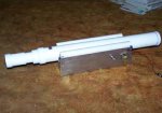
The input lens is 0.5" Dia @ -1.39" FL --- $54
That FL gives me opportunities for a shorter barrel.
Mike
That FL gives me opportunities for a shorter barrel.
Mike


 ;D
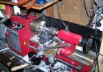
;D  ) Its also resting on a stand made of rubik's cubes if it wasn't wonky enough for ya.