Welcome to Laser Pointer Forums - discuss green laser pointers, blue laser pointers, and all types of lasers

LPF Donation via Stripe | LPF Donation - Other Methods

Links below open in new window

ArcticMyst Security by Avery

Please check my math.

WWC

0
Joined
Oct 26, 2014
Messages
19
Points
0
I have a 2W blue lasre in a housing, specificallyhttp://www.amazon.com/gp/product/B00HFHJBDI/ref=oh_aui_detailpage_o00_s00?ie=UTF8&psc=1 this one.

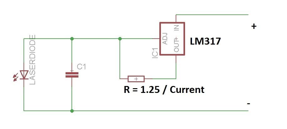
I am using the standard LM317 driver circuit.
This laser is rated to 1.8A I know it is not good to max it out all the time.

I am checking the voltage across a shunt resistor of 1 ohm directly in line with the diode. The voltage measures .216V or 216 milivolts. So Using I = V/R we get .216 / 1 OHM = I of .216 amps going to the diode?

Is this correct or did i miss something?

Thanks


Joined
Jan 29, 2014
Messages
12,031
Points
113
Yes, a voltage drop of .216 across one ohm is 216 ma. Is it a precision resistor? Some resistors can be 5, 10, 20 or so percent off of what they are marked. Shunts are normally much lower resistance to prevent too much voltage drop if you are going to keep it in line with your device. Leaving it in line at that current your device is then receiving .216 volts less than your supply voltage, increase the current by a factor of ten times and you then have 2.16 volts less supply voltage across your diode.

Shunts normally come with a voltage drop of 50 millivolts for what ever current they are made for at maximum. For 10 amps that would be .005 ohms. For 2 amps it would be .025 ohms for 50 mv of drop at full current, you would need to parallel 40 each one ohm resistors to get that low of a resistance. I realize you aren't intending on keeping the resistor in line, but thought I'd let you know what ever voltage drop you read across it, that much is missing from your devices input.
 
Last edited:

ARG

0
Joined
Feb 27, 2011
Messages
6,772
Points
113
Is the current not what you expected? Your math is correct.
As LaserProject said it could be the resistor.
 
Joined
Aug 14, 2013
Messages
2,655
Points
63
I don't know what you're doing, but the
M140 is generally run at 1.8A. The voltage
drop across the resistor should always be
1.25V. That means you should be using a
1.25 / 1.8 = 694 milliohm resistance and
the circuit below. A 1.2, 2.2 and 6.8Ω
resistor in parallel will get you close.

11711-diy-homemade-laser-diode-driver-lm317_components01_001.jpg
 
Joined
Jan 12, 2008
Messages
3,290
Points
83
The Lm317 is rated to MAX 1.5A, and the reference voltage will lower significantly even by then. You're better off getting a switchmode driver.
 
Last edited:

WWC

0
Joined
Oct 26, 2014
Messages
19
Points
0
I am using that schematic provided by Lighten Stalker. I have 2 one ohm 5% resistors in parallel there giving me right at .6 ohms. I am just using the one ohm resistor in line of the diode to check the current. But i think now the one ohm is much to high. The only reason i was checking the current there was to try and confirm the current going to the diode.

Another thing is my variable resistor does not go to 0. There is always a minimum of 23 ohms in the circuit from it. Could i just remover it from the circuit. All it seams to do it be able to turn the current down. Not sure why i would want to do this. I was planning on using it in a on / off status. I suppose if it was a very powerful laser i might want to adjust the current for a particular application, but i may be able to adjust the speed instead on this project.

So again the main thing i was trying to do was confirm the current so as to not burn out the diode before i even get started. What is the best approach or is setting it with the .6 ohm resistors going to be good enough.
 
Joined
Feb 5, 2008
Messages
6,252
Points
83
I am using that schematic provided by Lighten Stalker. I have 2 one ohm 5% resistors in parallel there giving me right at .6 ohms. I am just using the one ohm resistor in line of the diode to check the current. But i think now the one ohm is much to high. The only reason i was checking the current there was to try and confirm the current going to the diode.

Another thing is my variable resistor does not go to 0. There is always a minimum of 23 ohms in the circuit from it. Could i just remover it from the circuit. All it seams to do it be able to turn the current down. Not sure why i would want to do this. I was planning on using it in a on / off status. I suppose if it was a very powerful laser i might want to adjust the current for a particular application, but i may be able to adjust the speed instead on this project.

So again the main thing i was trying to do was confirm the current so as to not burn out the diode before i even get started. What is the best approach or is setting it with the .6 ohm resistors going to be good enough.

I am strongly against using potentiometers in laser drivers, along with that ages-old schematic.

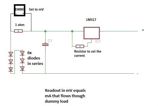
There's always a better way. Here is a simplified schematic:


If you need to test it with a dummy load:
 

ARG

0
Joined
Feb 27, 2011
Messages
6,772
Points
113
I am using that schematic provided by Lighten Stalker. I have 2 one ohm 5% resistors in parallel there giving me right at .6 ohms. I am just using the one ohm resistor in line of the diode to check the current. But i think now the one ohm is much to high. The only reason i was checking the current there was to try and confirm the current going to the diode.

Another thing is my variable resistor does not go to 0. There is always a minimum of 23 ohms in the circuit from it. Could i just remover it from the circuit. All it seams to do it be able to turn the current down. Not sure why i would want to do this. I was planning on using it in a on / off status. I suppose if it was a very powerful laser i might want to adjust the current for a particular application, but i may be able to adjust the speed instead on this project.

So again the main thing i was trying to do was confirm the current so as to not burn out the diode before i even get started. What is the best approach or is setting it with the .6 ohm resistors going to be good enough.

What is the power rating on your resistors?

I suggest taking Eud's advice. One set resistor is better than a pot.
 

WWC

0
Joined
Oct 26, 2014
Messages
19
Points
0
They are 2W resistors. I remove the pot last night and do have a stronger laser because of it.
 
Joined
Aug 14, 2013
Messages
2,655
Points
63
I am using that schematic provided by Lighten Stalker. I have 2 one ohm 5% resistors in parallel there giving me right at .6 ohms.

Two 1Ω resistors in parallel would make 0.5Ω,
giving 1.25 / 0.5 = 2.5A drive current. The
diode will not last long at that level.
 

WWC

0
Joined
Oct 26, 2014
Messages
19
Points
0
Ah ya right. Thanks for the correction. The real world resistance is .6 ohms but that still makes the current a touch high. I will try your suggestion of resistors ( 1.2, 2.2 and 6.8Ω ) to get closer to the mark.

Thanks
 
Joined
Aug 14, 2013
Messages
2,655
Points
63
I hesitate to believe this is truly 0.6Ω.
The actual resistance is going to be much
closer to 0.5Ω (500mΩ) for a couple of
reasons. "Best" case, both resistors are
exactly 5% over which would still give only
525mΩ. This is too low to accurately
measure with a 2 wire multimeter because
the resistance in the connections and leads
will add another 100mΩ or more to the
measurement. So unless you're measuring
this with a freshly calibrated 4+ digit 4
wire ohm meter using all 4 leads, this
measurement is suspect.
 

WWC

0
Joined
Oct 26, 2014
Messages
19
Points
0
I have no valid argument for the resistance and would tend to go with your claims. I am using a 25 yr old Fluke that is about .5 ohms off, so i was subtracting that from the read value. Best thing would be to up the ohms to a safer value.


Top