Welcome to Laser Pointer Forums - discuss green laser pointers, blue laser pointers, and all types of lasers

LPF Donation via Stripe | LPF Donation - Other Methods

Links below open in new window

ArcticMyst Security by Avery

Ex government research laser

Morgan

0
Joined
Feb 5, 2009
Messages
2,174
Points
0
Hi All,

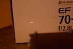
As well as getting my Heruurscience gear recently, I picked this thing up for £50 from ebay. (I will get round to buying an LPM Laserbee. I promise!!!).

It was a bit of a gamble from the picture shown in the auction but after getting it I think it paid off. There was another one but by the time I realised what I'd got, it was gone.

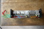
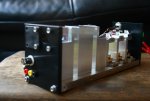
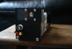
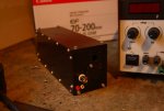
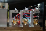
Anyway, here are some pics. I gave it the tear-down treatment for you but when it's all together I really would be happy to drive a truck over it! Being ex-government research equipment, the build quality is fantastic. Nobody was in any kind of rush to build this thing.

So far I determined that:

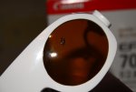
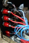
All three diodes visible are IR, (wavelength unknown at this point).
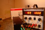
All run at around 1.8V and upto 3.5A, (still learning the testing procedure so these values are open to debate), and all burn quite nicely although not evenly across the beam line.

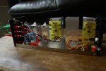
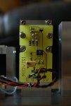
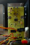
There looks to be another diode in the sub-assembly immediately to the right of the IRs and this is powered be the associated circuit, (labelled MIOVIS1). I hazard a guess that the other assembly is to measure the first? Both have another input via the connection you can see on the outside of the box, (can't remember the name for them).

Any guesses as to the purpose?

Regardless of the original use, I think it wasn't a bad buy. Bit random but nice to get my hands on a proper bit if kit!

Looking forward to your input.

M

edit* I do have more photos but didn't want to swamp the server! *
 

Attachments

  • DPP_0351.JPG
    DPP_0351.JPG
    229.2 KB · Views: 323
  • DPP_0356.JPG
    DPP_0356.JPG
    206.9 KB · Views: 294
  • DPP_0352.JPG
    DPP_0352.JPG
    191.2 KB · Views: 278
  • DPP_0359.JPG
    DPP_0359.JPG
    210 KB · Views: 285
  • DPP_0362.JPG
    DPP_0362.JPG
    218 KB · Views: 283


Asherz

0
Joined
Jan 18, 2009
Messages
1,623
Points
0
I'm still confused, what is it and what is it or what was it used for? ex-govermant sounds interesting :)
 

diachi

0
Joined
Feb 22, 2008
Messages
9,700
Points
113
I want to see some pictures of the outside with the end beam coming out ! :D

It looks very nice, but now that I have seen the insides, I want to see the whole thing :p

Regards,

Adam
 

Morgan

0
Joined
Feb 5, 2009
Messages
2,174
Points
0
As to its use, Asherz, I'm just as confused as you are! The IR setup is as you see it. Each has a small cylinder lens, (are they called GRIN lenses?), that puts a line through each of the prisms and then through the two sub-assemblies. I'm not convinced they truly combine as they are slightly staggered in height, (see pic 2). Just going on the geometry I think the aim is to just give a thicker beam but more testing will tell.

I'm hoping they are close enough to 808nm to be the start of a kick-ass DPSS number but I am in the dark at the moment, (pun intended!)

The confusing thing are the sub-assemblies. They seem to be independent of the IR but share a beam path. I don't know if you can see from the pics but if you look at the first circuit, near the top there are the familiar three legs of an LD. This goes through a dichro, (hope I'm using correct terminology there), and follows the IR beam. Then through another dichro to what looks like a sensor in the second circuit. Both these are connected to the chrome input/outputs at either end and are powered seperately through the tiny plugs; also on either end. I have put 5V and a few mA through the diode circuit but could not see any light.

I did hook up two of the IR diodes together in series though. This gave a beam just as bright as one but I guess was only making each LD work half as hard. I figured this was a reasonable risk to take as they appear to have some protection, (pic 5 in 1st post). Maybe the more technical folks can confirm this.

Adam - I will put it all together for you and see if my DSLR is IR sensitive. It's pretty dull to look at in one piece but I will indulge you!

It may end up being a completely useless bit of kit but as an educational aid I'm already getting my money's worth. Pics of my new 200 -540nm, 800-1100nm OD4 googles with a lesson-learning hole in them will be posted tomorrow!!!

That's all the pics for now. More tomorrow.

M
 

Attachments

  • DPP_0360.JPG
    DPP_0360.JPG
    255.7 KB · Views: 252
  • DPP_0366.JPG
    DPP_0366.JPG
    190.7 KB · Views: 250
  • DPP_0365.JPG
    DPP_0365.JPG
    176.6 KB · Views: 247
Last edited:
Joined
Jan 7, 2007
Messages
6,309
Points
83
Might this be 3 IR lasers combined with 1 visable targeting diode ?? I seem to see a BIG prism in there.

Mike
 

Morgan

0
Joined
Feb 5, 2009
Messages
2,174
Points
0
I had thought that Mike but I can't get the little one going to confirm that. There are no BIG prisms, just the ones for the IRs. Looking at the pic through someone else's eyes it looks like there is one on top of the first sub-assembly but that's reflections from the milled surface. The dichro IS there and you can see the beam path for that going through the large central block, (doesn't appear to be anything in that block. Just a hole.), and back to the second. My thinking is that if it were just to target, why so complicated? There are also what look like diverging lenses in the sub-assemblies too.

Sometime I will just have to bite the bullet and remove them to get a better look.

M
 
Joined
Sep 12, 2007
Messages
9,399
Points
113
The extra stuff is probably to help clean up the veritably awful beam of an IR diode. The second optic closest to the aperture might be just a piece of glass to reflect a portion of the beam for measuring/stability purposes.

with all three running at 3.5A, that's about 10W of IR. A Laserbee can't help you there. don't forget goggles though.
 
Joined
Feb 11, 2008
Messages
730
Points
0
It appears to be an offset phased array diode laser. I have some of these units, nowhere near as pretty, but do the same thing- combines multiple diodes with beams slightly offset to form a high power multmode beam with nice beam characteristics-most importantly maintenance of polarization and point source quality factor.
 

Morgan

0
Joined
Feb 5, 2009
Messages
2,174
Points
0
Now that's some proper technical talk Chris! Can you elaborate a little. Pretend you're explaining it to a small child!

Why is maintenance of polarization and point source quality factor so important? A link to a relevant resource could help as I feel it may take me a while to find that on my own.

A link for an explaination of multimode and its uses would be handy too if its not something that's easily explained in a post. I'm sure I'd be able to find this in the Bible, (Sam's FAQs), but there are other sources I won't be aware of. Does the subject of mode-hopping link into multimode?

Thanks,

M
 

diachi

0
Joined
Feb 22, 2008
Messages
9,700
Points
113
Now that's some proper technical talk Chris! Can you elaborate a little. Pretend you're explaining it to a small child!

Why is maintenance of polarization and point source quality factor so important? A link to a relevant resource could help as I feel it may take me a while to find that on my own.

A link for an explaination of multimode and its uses would be handy too if its not something that's easily explained in a post. I'm sure I'd be able to find this in the Bible, (Sam's FAQs), but there are other sources I won't be aware of. Does the subject of mode-hopping link into multimode?

Thanks,

M


Multimode basically means that the diode has several different emitters. So you end up with a beam that when unfocused looks like many lasers beams at once. It can be a bit of a pain to get a nice beam from a multimode laser diode, never mind 3 of them combined to make the task even harder !

If I still had that 1W IR laser here I'd show you the beam of that. the dot has around 9 or so different dots in the one square dot which show the different number of emitters. The beam is usually square too.

Like here : http://upload.wikimedia.org/wikipedia/en/b/be/Hermite-gaussian.png

If you look at many higher powered red diode lasers, say a 635nm 1W laser . The beam specs will be horrible, and the beam will be square, this is due to the diode used being multi-mode.
 
Last edited:

Morgan

0
Joined
Feb 5, 2009
Messages
2,174
Points
0
Ah-ha, (exclamation of understanding, not the band!), that's why the diode bars that I've seen specs on quote the number of emitters.

This may also explain why the beams from this thing, although all similar in dimension, have light and dark patches.

... Hang on while I go take some pics.

Back in a tick...

M
 
Joined
Feb 11, 2008
Messages
730
Points
0
It probably was a pump source for some sort of DPSS laser. As you know the best you can get out of a fiber cable is the diameter of the fiber core, when you do it this way instead, You can use optics and get the beam to be as small as the emission area of the laser channel of each one of the diode lasers.

If they use prisms and lenses right they can get the 3 beams to overlap forming in effect a laser diode beam with the spot size from ONE laser diode at 3x the power.

That in short, is what I believe this unit was originally for.
 

suiraM

0
Joined
Aug 31, 2008
Messages
206
Points
0
Multimode basically means that the diode has several different emitters.

Not quite. A mode is a math term to express a resonance.

Imagine that the surface of a pond is like a cross-section of a laser beam. Drop one pebble, and you get a single transverse mode (TEM[sub]00[/sub]). Drop more pebbles, and you get multiple transverse modes. Regardless of focusing, if the laser is operated with multiple transverse modes, there will be a pattern of lobes in the beam (not multiple beams). The number of emitters is not what determines the number of lobes; you can join many single mode emitters with a grating to get a single mode output, or you can have a single emitter with multimode output.

Also, there is the longitudinal direction, which can be compared to a pipe organ. A big pipe will sound rich, not just because the note (wavelength) is low, but also because the length of the pipe can sustain several longitudinal modes at once. Most lasers of any kind will have multiple longitudinal modes, which shows up as very fast intensity noise (unless they are all in sync, in which case it will look like the output is pulsing quickly, so-called "mode-locked operation").

For a hobbyist, the transverse mode profile is the most important one, as it determines the appearance of the beam and the tightness of the focused spot. The exception is when you are pumping a greenie, where you also want a single longitudinal mode (because that will improve pump efficiency, and thus heat, power, etc.)
 

Morgan

0
Joined
Feb 5, 2009
Messages
2,174
Points
0
... Sorry, i wasn't back in a tick. More photos will follow but I had a couple of things come up. Maybe we can clear a few things up when the pics are posted. All this is really good stuff and I'm trying to follow but I need time to ingest it all. Please be patient with me and keep checking in on this post.

The pond surface analogy I think I understand. The pipe organ kind of makes sense as I used to be a piano technician and it sounds like you're explaining something similar to string harmonics. The longer the string the richer the sound, etc. How this applies in this case will just take some time to establish in my brain.

Trying to keep it real....


M
 
Last edited:

Morgan

0
Joined
Feb 5, 2009
Messages
2,174
Points
0
So here are some more pics. (all together with the beam coming out Adam!)

It turns out my DSLR is IR filtered so you can actually see the beam shape quite clearly. As I mentioned before, there are brighter patches at either end of the line and the middle is dimmer. I hooked up two of the diodes in series. Diode one and three, (the ones showing in these shots), have the variation whilst number two is brighter in the middle. Does this give a clue as to the health?

They will each run up to 3.5A but for the photo I just got them to shine.

I also included a shot of the devastated goggles that took a hit the other day whilst testing. (NO EYES WERE HURT IN THE MAKING OF THIS PHOTOGRAPH!!! :)) I was checking to see how protective the goggles were so placed them in front of the beam and checked with my IR sensitive camera if any was visible after the goggles, (I was wearing my other pair at the time!). No light was visible until 6-10 seconds later. I was a little confused until I smelled the smoke and saw the damage. All I can say is that this was a sobering experiment and I'm glad I was not wearing them at the time!

Enjoy.

M
 

Attachments

  • DPP_0371.JPG
    DPP_0371.JPG
    194.5 KB · Views: 184
  • DPP_0372.JPG
    DPP_0372.JPG
    162.4 KB · Views: 185
  • DPP_0373.JPG
    DPP_0373.JPG
    198.6 KB · Views: 189
  • DPP_0374.JPG
    DPP_0374.JPG
    163.5 KB · Views: 196


Top