Welcome to Laser Pointer Forums - discuss green laser pointers, blue laser pointers, and all types of lasers

LPF Donation via Stripe | LPF Donation - Other Methods

Links below open in new window

ArcticMyst Security by Avery

DIY Blue Beam Dye Laser

Joined
Jun 24, 2009
Messages
364
Points
0
Wow! What a cool laser! I've looked up the info on the technology of dye lasers... not as easy as it looks, but certainly another interesting project. I have a few high grade dyes at home (including Alizarin Yellow B) so it might be quite an interesting thing to attempt.

Too many cool projects, not enough time! AArgh! :eek:

Robert


Benm

0
Joined
Aug 16, 2007
Messages
7,896
Points
113
You need a pretty fast protection diode, at 15 kHz an 1n400x series is likely too slow - those are really only intended as mains rectifiers and good for little else.

About the frequency: its such an exact number (15625) because its derived from the scan line frequency of the tv set - 25 frames per second, 625 lines per frame. This does not mean you have to drive it at exactly that frequency to get it to work, though its likely to be its optimum.
 

Benm

0
Joined
Aug 16, 2007
Messages
7,896
Points
113
Side note: definition of "accident" related to high voltages: "when you're playing with high voltages, if you start to feel all the hairs on your body rise up straight and start to spark at the extremities, look a blue/violet halo around your body, and start to smell "fried chicken" like, you probably had an accident"

Should read...


"when you're playing with high voltages, if you start to feel all the hairs on your body rise up straight and start to spark at the extremities, look a blue/violet halo around your body, and start to smell "fried chicken" like, AND you live tell, you must be a very lucky man

;)
 

HIMNL9

0
Joined
May 26, 2009
Messages
5,318
Points
0
^ LOL, true :D

BTW, about the diodes ..... old PC power supply units are all switching , and almost all works at 100 KHz or more ..... maybe the power diodes at their output stage can be a cheap and efficent alternative to high cost schottky power diodes (other than this, is not easy to find a specific schottky diode in all the countries, in components shops, where instead a broken pc PSU can be found, probably for free, in almost any pc shop ;)


Edit, i'm too curious, so i just mangled 3 pc PSU that i have here broken, to throw away, and found these 3 models inside

attachment.php


The the PR3004 ones, according with the datasheets, are "1000 V 3A fast recovery rectifier", rated for 150 nS (nanoseconds), the S16C40C is a dual 16 A 40 V schottky rectifier, and the SBL1040CT is a dual 10 A 40 V schottky rectifier ..... not bad, for recovery parts :) (and are all working ok, cause 90% of the pc PSU, when blow, burn the main power part ;))
 

Attachments

  • schottky diodes.jpg
    schottky diodes.jpg
    210.8 KB · Views: 11,650
Last edited:
Joined
Jun 12, 2008
Messages
1,199
Points
48
You need a pretty fast protection diode, at 15 kHz an 1n400x series is likely too slow - those are really only intended as mains rectifiers and good for little else.

About the frequency: its such an exact number (15625) because its derived from the scan line frequency of the tv set - 25 frames per second, 625 lines per frame. This does not mean you have to drive it at exactly that frequency to get it to work, though its likely to be its optimum.

Hmm, good point, I was mainly surprised at the very exact figure, I would like to see a flyback tuned for exactly that freq. :san:

I have driven plenty of these chumps, never went down into the audible range (yuck), they seem to work best in the 20-30kHz area for me if they are taken from a TV. But it really depends on he flyback.


Well the flyback circuit from the TV, will have a very decent high voltage diode on it, most likely in the TO-220 package, just with two "legs". Check for that, if you need a nice diode.


Which circuit are you going for in the end?
 
Last edited:
Joined
Apr 28, 2009
Messages
2,416
Points
63
The circuit that I posted above is apparently not very good for driving the nitrogen laser. That was according to an engineer that I showed the circuit to. He says that the reflected inductance from the secondary as the laser cavity fires comes back into the primary and causes a problem. I'm still thinking about which circuit I will use. Instead of using a 555 timer, I'm thinking about using the LM3525 for the PWM(Pulse Width Modulator), and using a snubber circuit for protection.
 
Last edited:

HIMNL9

0
Joined
May 26, 2009
Messages
5,318
Points
0
^ Is exactly for this reason that i've suggested you to put a fast diode in parallel to the primary ..... ;)
 
Joined
Apr 28, 2009
Messages
2,416
Points
63
Will that diode be enough do you think? Or what else can be done? Also how would an LM3525 be substituted in the circuit? Thanks for your help once more friend! :D
 

Benm

0
Joined
Aug 16, 2007
Messages
7,896
Points
113
Those diodes from the PSU look suitable to me - just give them a try.

As far as any pulse going back from the laser to the flyback transformer: I was thinking you'd use the flyback to charge the capacitor plates through a resistor. Perhaps it would help to put an inductor in series with that as well, since that'd pass the charging DC just fine, but pose a big resistance for fast pulses.
 

HIMNL9

0
Joined
May 26, 2009
Messages
5,318
Points
0
Uhm, the LM3525, according with my datasheets, is just a 5V switch for USB ports ..... don't contain any oscillator circuitry.

Are you sure that the part number is this ?

About the diodes, i think that the single ones are the best choices, if you find them, cause the 1000V reverse voltage ..... the schottky ones are more fast, but have only 40 V rated, and after all, at 15 / 16 KHz, a fast diode is enough ;)


Edit: Benm suggestion is good, too, just choose the value, for be sure that the circuit don't go in "resonance" with the spark-gap frequency, and cause problems ..... just for experiment it, maybe also just an old ferrite rod (ex AM antenna) with 40 or 50 turns of 0,5 mm dia or similar insulated wire can be good.

Always remembering that this is the HV side :whistle: ..... :D
 
Last edited:

3zuli

0
Joined
May 30, 2009
Messages
810
Points
28
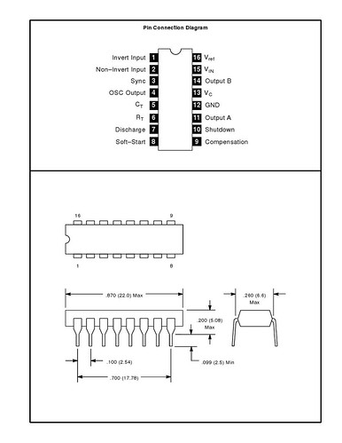
or you can use TL494, that's switching supply controller. contains oscilator with PWM and the best thing is, that it (or its clons) is used in most PC PSUs :D
 

HIMNL9

0
Joined
May 26, 2009
Messages
5,318
Points
0
About NTE, i found only preliminary datasheets around, no internal schematics or details, so don't know for sure, sorry ..... anyway, perhaps all these components are mainly for drive power components in PSU units ..... may requires some feedback circuitry, for work good.
 
Joined
Apr 28, 2009
Messages
2,416
Points
63
^ Here is the internal circuit for the SG3525, which is similar or the same as NTE1721.......

SG3525inside.gif


I found this circuit for a plasma globe PS. It is intended to run at high frequency AC on the secondary, but could be modified to put out DC for the nitrogen laser correct?

Schematic.gif
 
Last edited:

HIMNL9

0
Joined
May 26, 2009
Messages
5,318
Points
0
Uhm, it can be used, i think, but you really don't need a pwm for that, just a flyback with an oscillator, cause, after all, the high voltage unit, don't control anything, is just a power supply (btw, i have a plasma ball that use just a 4007 as oscillator and a TIP120 as power stage, for a flyback transformer ..... cheap, but works :))

I mean, no reason for complicate your life ..... just try a schematic that can give you a decent DC output for the resonant cavity, and you're ok.

Also, for turn it DC, you need high voltage capacitors and diodes (usually 10 KV ones) ..... not cheap.

Oh, just as my usual DIY maniac side, i remembered, there are some very good high voltage units inside the old photocopiers, the big old ones have the better ones (are used in the transfer process, for charge the paper and he drum surface, and transfer the toner powder from one to the other via electrostatic charge)

In the past, i recovered some 5600 V and 9800 V units, from some old xerox and canon, and these units usually are ready-to-work ..... mean, a box or a circuit that have already all on, flyback, oscillator, driver, you just need to power up it ..... and if you can find some of these things from some scrap deposit, usually they come for free :)

Just as idea.
 
Joined
Apr 28, 2009
Messages
2,416
Points
63
I will ask the engineer that I talked to earlier to redesign the above circuit. If he comes up with anything good, I will post it. Thanks again!


Top