Welcome to Laser Pointer Forums - discuss green laser pointers, blue laser pointers, and all types of lasers

LPF Donation via Stripe | LPF Donation - Other Methods

Links below open in new window

ArcticMyst Security by Avery

B&W Tek BWB-10-OEM 473nm Help!

Fiddy

0
Joined
May 22, 2011
Messages
2,726
Points
63
G'day,

Got my 473 labby today :)

I have many questions,

4731.jpg


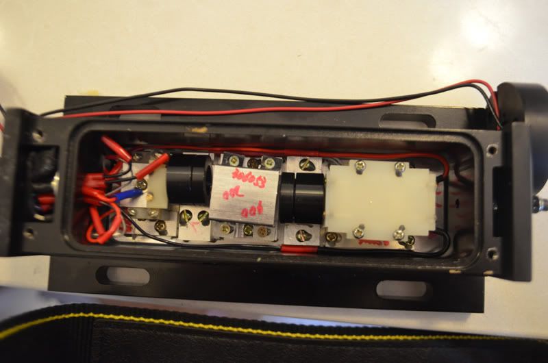
1. From left to right does i go:
Pump Diode -> Lens -> Prisms -> Lens -> Crystals -> Output?


2. Where are the IR filter(s) located?


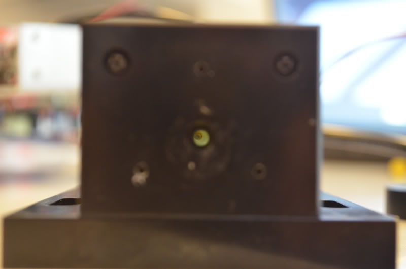
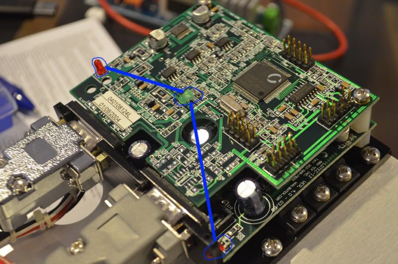
3. What does each of these 3 LED's indicate?
I read the green one indicated its stable when it goes out?


driverboard.jpg


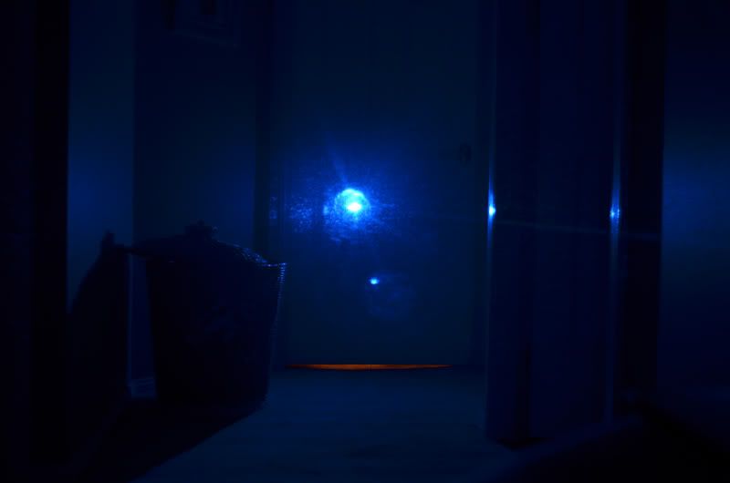
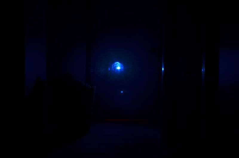
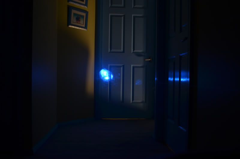
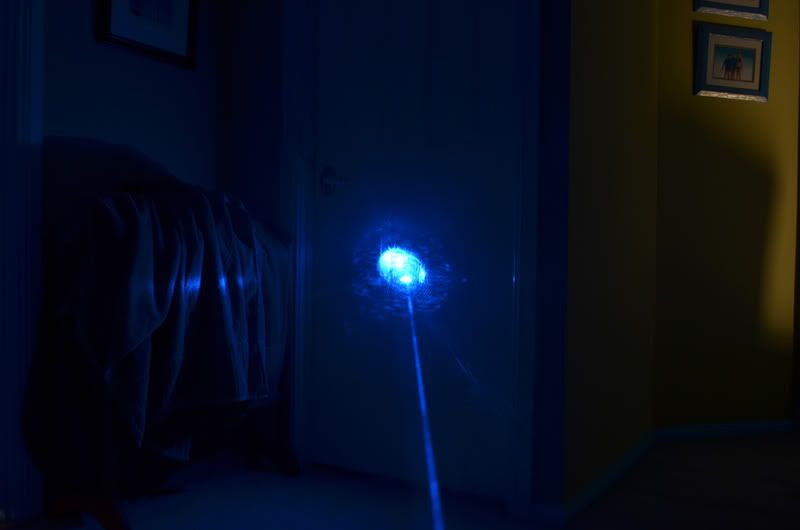
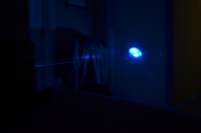
4. Where is a good place to start attempting to achieve better beam specs?

As mine aren't too good atm:

4733.jpg

4732.jpg

4731-1.jpg


Thanks in advance,

Fiddy.


Joined
Aug 15, 2009
Messages
1,443
Points
48
1) Correct
2) after the crystal set, probably attached to the case or front plate
3) I have no idea, I can try to see if I can understand the behaviour of mine if you want.
4) First determine the type of distortion your beam has. It looks a bit uneven for a TEMxx mode so first check to see if all the surfaces after the crystal set are clean and do not obstruct the beam.

If they look all clean and clear try adjusting the lens right before the crystal set. It's fixed, but pushing it moves it slightly. You'll probably need to push it closer or away from the crystal set, if a sideways motion helps the beamprofile then the crystal is dirty/damaged. In my case pushing the lens closer to the crystal set made it jump to TEM00. What I did was loosen the screw and that made the lens go forward a bit, I haven't fixed it permanently yet.
 

Drew

0
Joined
Oct 6, 2010
Messages
226
Points
0
Got mine today too. Search the thread: B&W Tek BWB-10-OEM - 473nm 10mW . There's quite a bit of usefull info there, seems like a double convex and a collimating lens does a good job with the divergence. Your spot/dot does look a lot nastier than mine though. It looks like the beam is getting pulled up and left from a misalignment somewhere? Good luck
 
  • Like
Reactions: GBD

GBD

0
Joined
Oct 25, 2010
Messages
783
Points
0
The IR filter is located behind the optical feedback and its mount(circular front of the laser, held in place by three bolts, with two wires comming out of it). and is just glued on the housing.
In your first picture you shifted the OF to the side, now there is another plate that you must remove to get to the filter. (two more bolts)

Removing this unit will reveal the IR filter, for some reason mine was dirty and upon removing the filter all together the output cleared itself up to a nicer profile. (before doing that my "dot" looked like some firework effect)

keeping the optical feedback off, will result in no regulation, which seems to make the laser output about 2X its running power (although more unstable, ive gotten ~30mw of mine and nothing failed.. so try running without it at your own risk)... but it can always be bolted back on after removal if you so desire.

a double convex and a collimating lens does a good job with the divergence.

Very good point, IIRC Dont lase me bro figured that out originally, but thats what I did to my unit also to correct the output after the profle was cleaned up by ridding of the dirty filter. (divergance wise, there is no collimators of any kind after the crystals)

http://laserpointerforums.com/f48/473nm-lab-pictures-65908.html

I got some pictures in that thread with the original output, and that after the removal of the filter and addition of a collimator.
 
Last edited:
Joined
Oct 26, 2007
Messages
5,438
Points
83
What kind of glue did they use on that filter and the wire mount in the back? I'd like to reuse some of the parts that are glued up, but haven't found a way besides mechanical removing to get rid of it. Any ideas?
 

Fiddy

0
Joined
May 22, 2011
Messages
2,726
Points
63
what is a OC mirror and where does it live?

Also am i meant to remove the glue on the bolts that hold the components still?
 
Last edited:

Fiddy

0
Joined
May 22, 2011
Messages
2,726
Points
63
UPDATE

had my first play with the mounts on the lens,prism and crystal.

looked down the apperature and you could see it was off:

4738.jpg


did some adjusting with my IR glasses on

Got it to this:

4736.jpg

4737.jpg
 
Joined
Oct 26, 2007
Messages
5,438
Points
83
Remember that you need to keep the crystals sealed from the air or they'll degrade. Those sealed boxes in the interior may only be for short term sealing. The rest of the chamber probably makes it more permanent.
 

Fiddy

0
Joined
May 22, 2011
Messages
2,726
Points
63
I planned on re-aligning the crystals, so i opened up the white platic box, careful not to touch the OC mirror, i popped off the crystal set but the TEC holding all the components off the white box came off with it :( do i just glue it back down with some thermal adhesive?
 
Joined
Aug 15, 2009
Messages
1,443
Points
48
Realigning the crystals is very difficult, it's all glued down so it won't move to start with. If you get components loose you'll need precision mounts for all the components, an alignment laser, lots of tedious work and a way to fix the components at their position again.
But you probably won't gain much by it. Unless you can determine from the dot profile that the cavity alignment is a problem and you have the equipment and skill I'd recommend to leave the cavity as it is.
 
Last edited:

JLSE

1
Joined
Dec 13, 2007
Messages
3,580
Points
0
I planned on re-aligning the crystals, so i opened up the white platic box, careful not to touch the OC mirror, i popped off the crystal set but the TEC holding all the components off the white box came off with it :( do i just glue it back down with some thermal adhesive?

Get rid of the white plastic walls, no need for them, they are not there
to seal anything. My guess would be to absorb IR but that would be it.

If you gently move the TEC around you will find its original 'seat'. Practice
finding this 'seat' then mix up some quick set epoxy and get it back in place.

Just be sure to put something with some weight on the mount while the epoxy
sets.. To verify its in the right position, just power up and have a look at the beam.

I had a few do this very same thing.. The fix is quick and easy.. :beer:

Wait til the glue is good and cured, proceed with your alignment.
 
Last edited:

Fiddy

0
Joined
May 22, 2011
Messages
2,726
Points
63
Ahh ok, i thermally glued it back on and its good.

I rotated the crystal set 180 deg, it took some splash away but there is still some left.
 

JLSE

1
Joined
Dec 13, 2007
Messages
3,580
Points
0
Flipping it around will help with some splash & modes, but wont get rid of it all..
Though you can sacrafice power for a better mode in most cases.
You can also try lifting / tilting each side of the LBO holder just a hair.. In other words
you are rotating the crystal which in some cases will give you more mW.

If this works, you can use a piece of foil to shim the mount and work at a higher output.

You're lucky it was the glue and not the TEC itself. I have had several that the TEC

split in 2, and no way to repair other than a new TEC..
 
Last edited:

Fiddy

0
Joined
May 22, 2011
Messages
2,726
Points
63
Yeah thank god the TEC didnt pull itself apart.

ok sweet will, pack out the crystal with some foil shims.

Ive got a nice TM00 dot atm, just some splash.

Thank for the tips!


Top