Welcome to Laser Pointer Forums - discuss green laser pointers, blue laser pointers, and all types of lasers

Buy Site Supporter Role (remove some ads) | LPF Donations

Links below open in new window

FrozenGate by Avery

1000mW Rominsen 836nm C-Mount

JLSE

1
Joined
Dec 13, 2007
Messages
3,580
Points
0
So I decided to get into the C-Mount diodes, as im gearing up for some 532nm builds. Alignment is going to be critical and I wanted to get a feel for the setup. There isnt too much info out there, mainly pics, which I can gather a better understanding. I have seen C-Mount diodes up to 5000mW (5W), which is probably too much power for the pump medium I intend to use.

The diodes which im currently using are 1100mW @ 836nm originally meant for communication applications. The interesting thing with these is that there is no visible light whatsoever. 808nm give a nice faint red glow but are still visible to some degree. So while they may not have a pretty beam, they are super destructive and can only be seen with an IR cam or nightvision goggles.

My first test assembly was more or less a mock up to get in the swing. The only problem I see is the heat these little buggers generate :o At full output, your lucky if you get 2min's before it gets nice and hot. Im going to build another today with a monster heatsink, and possible active cooling.

The next challenge is going to be the power supply, I ran this one straight off a single lithium which is only rated for 880ma, so im going to have to find a circuit that can deliver 1600ma from two of these cells and not contribute to the heat that the diode produces.
In the video, its running at full tilt using 12vdc through an LM317 mounted on a big heatsink. Any suggestions for a suitable circuit would be great :)

While these are multimode, they seem to behave a little different than a 808nm 9mm package, in that I get a decent collimated beam from a standard Axiz acrylic lens ::)

Enough with the talk heres the pics and the vid. ;D


Enjoy.


[media]http://www.youtube.com/watch?v=dJWbnprQNYs[/media]


P1210019.jpg

P1210035.jpg

P1210099.jpg

P1210076.jpg

P1210121.jpg

P1210146.jpg

P1210173.jpg

C_Mount_1600ma.jpg


isn't 836nm the wrong wavelength for pumping crystals - don't you need 808nm?
 
robjdixon said:
isn't 836nm the wrong wavelength for pumping crystals - don't you need 808nm?


These arent for pumping, just a mock up build to get the hang of the c-mount setup. The funny thing is they will light up a crystal set with maybe 2% efficiency, but these diodes are for playing with ;) I am going to order some 808's when I get the layout right :)
 
For a 1w or better laser, I use a larger battery. In my 1 and 2w handhelds, I use an 18650 lithium, 2500mah battery. For my 4w handhelds (my 808 and 960 nm) I use 2 x 25500 lithiums (C size). You need anough battery that the load of the diode at full power isn't going to cause a voltage drop from the battery that causes the regulator to drop out of regulation. Since c-mount and other IR diodes are normally positive ground devices, I usually use a negative side regulator. A positive side regulator can be used, but would have to be located between the positive battery terminal and positive ground. (regulator buried in laser tailcap?) LM317 is good up to 1.5a. If you need more, substitute an LM350 (3a) or an LM338 (5 to 7a) for the LM317. For a negative side regulator, the 7135 based disks from DX work OK. Problem with these is they don't usually allow an output capacitor to be used. Of course, you could use a negative variable regulator complement to the LM317, such as the LM337T.

You have an interesting mount, heatsink, and focussing assembly! Nice metalwork! Where your torx setscrew holds the diode to the head, you might want to machine a little "backer" heatsink that the torx setscrew could hold in place against the back of the diode in order to gain even faster heat removal. Of course, the host does have limited space ... This would also alter your regulator placement. It's quite a juggling act.

I've found that when buying c-mounts, that a good product photo is very useful. What we need for easier collimation is a narrow, long emitter die. An example of this is the 2w 808nm c-mount sold continuously on ebay by seller "snoctony". I have bought several of these and always get a long, narrow die. Collimates to a burning point with an aixiz lens. My 960nm 4w diode is also a long, narrow emitter die. Again, easily collimated for burning. On the other hand, my 808nm 4w diode has a wide, short emitter die, and emits more like the bar-line emissions of my larger (20, 40, 100w) diode bars. This is much more difficult optically to deal with.

With your obvious high level of metalworking skill, you could easily produce an entire custom host! Very few people make their own dpss from scratch. Be looking forward to your finished project! Great photos, by the way.

Bill.
 
Thank you for the very useful input :)

There are a few obsticles I can see that will require some work so far. I think a bigger host and heatsink FOR SURE! Im going to have to accomadate a larger battery bank, and get rid of this heat. My fingers were sweating holding the module during the first couple of tests. Also both my meters tapout around 1100mW :'( so getting the readings on the pump if I go for a 5watt will be a pain. I think I will start with an 808nm of 2watts, as I have already made a 300mW 532nm with a 1watt 9mm also from snoctony.

I will order a couple of the LM338's from digikey today, and give it a go. I also have 2 18650 lithiums but they ran dry when I left my LPM running, and now they wont charge. They were new fresh batt's, is there a way I can revive them? Ive heard there is a way, but cant find the link.

Also, snoctony sells cmounts with fast axis lenses, can they be removed? I have had only bad luck and burnt crystals every time I use optics between the pump and the medium. >:(
 
Are the lithiums protected? If so, the protection circuit could be the cause. One of mine was in this same condition. I did the following non-recommended procedure. For brief periods, half second at the most, I connected my 5v bench supply to the battery. I repeated these brief zaps a few times, and the battery somehow "reset" and was able to charge. It has worked normally ever since. If the protective circuit is dead, cut it off or bypass it and use as an unprotected cell, with the appropriate cautions. There was a thread months ago about lithium battery issues and fixes.

I don't know if the fac lens can be removed from the snoctony diode because I've never tried. I make IR burners.

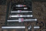
Attached is a photo of some very functional IR burners. At the very top are my micro red 200mw and my DX200 for size reference. My 1w 808nm (snoctony 9mm diode, 1 x18650, DX 1400ma regulator) is next, then the 2w 808nm (snoctony c-mount w/fac, 1 x 18650, 2 x DX 1400ma regulators), then my 4w 960 nm (SDL-6380C diode, 2 x 25500, 4.8a regulator). At the bottom is the 4w 808 nm, shown apart to see the head assembly.

Bill.
 

Attachments

  • Oct1108D200_001_2.jpg
    Oct1108D200_001_2.jpg
    119.1 KB · Views: 1,620
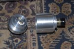
This is a closeup of the 4w 808nm head.
 

Attachments

  • Oct1108D200_002_3.jpg
    Oct1108D200_002_3.jpg
    124.1 KB · Views: 761
Okay, took another run at this. I made a larger heatsink to cope with the temperature, and put a little more time into the setup. I figured starting from scratch would give me a beeter result, and this module has certainly done that. The only problem ive hit is using the LM317. Even though its on a big a$$ heatsink, the 317 does fine, but the 25 turn 100ohm trimpot burns up and I can control the current? This would be a first for me, I had thought the first driver I was using was defective so I made another and the same thing happened. I didnt think that much current went through the pot, but it gets hot enough to burn the fingers! I am absolutely going to have to use a different driver for this diode or im going to be dealing with unescesary heat, and too much current going into the diode.

Heres the updated pics, but this module will not fit in the Rominsen body and needs a custom host :)

I like the fact that with the C-Mount and a transparent rear dust cap, allows for viewing the diode in action, you can literally stare down the cavity and get some interesting pics!

P1210225.jpg

P1210209.jpg

P1210419.jpg

P1210450.jpg

P1210321.jpg

P1210483.jpg

Untitled-14.jpg
 
A couple more pics :) And the retro He/Ne aluminum host. Must change the warning label to
'Low Voltage'  though :-?

P1210510.jpg

P1210538.jpg

P1210535.jpg
 
On the LM317 type driver, all of the output current does go through the pot. This is why we don't see a pot used in higher current incarnations of the LM317 circuit. If you absolutely need variable output, the pot would become large and be wirewound. You would probably need to alter the driver design. This could be done by using a transistor where the pot is. A transistor rated for this load would be TO-220 sized, you would use a multi-turn precision pot to control the transistor's base, varying in turn the transistor's resistance. Something like this is best breadboarded and tested with a dummy load. I made a variable driver like this for a bluray last year. It can work. Again, nice metalwork! :)
 
I think I should go with a resistor then, how many watts would be suitable? I have not used the 317 at this current before. I think 1100ma should be fine, but I dont have a spec sheet for these diodes. I tried to set the output of the laser to 1000mW bang on, and then measure the pot, and replace with an appropriate resistor. But as is, the laser is either at full tilt or off >:(

Im also wondering why my LaserBee LPM says 'overflow' on the screen @ 1050mW but the PC interface on my laptop and resulting graph keep climbing beyond the max of the unit? Strange indeed, but a very welcome surprise ;D

From a cold start it hits 1200mW and gently falls off :o
 
Thanks for bringing that to my attention wannaburn....

At the time the Firmware was programmed... we didn't think there we guys like
you who were going to take the LaserBee I to its maximum power level. ;D ;D
There will be a Firmware change for the 3rd Generation PCBs. 8-)

The reason that the LaserBee I is locked at 1050mW is that the Thermopile
coating is rated to 1050mW by our in house tests to be a repeatable safe
maximum power level.
We actually tested to 1200mW and had no degradation of the coating at that
power.
We could have easily marketed the LaserBee I as a 1200mW LPM to increase
sales... but we decided to stay on the long term safe side and included a margin
of coating safety. ;)

Any use over our rated 1050mW max rating is not recommended.. and you do
so at your own risk.. :)


Jerry
 
lasersbee said:
Thanks for bringing that to my attention wannaburn....

At the time the Firmware was programmed... we didn't think there we guys like
you who were going to take the LaserBee I to its maximum power level. ;D ;D
There will be a Firmware change for the 3rd Generation PCBs. 8-)

The reason that the LaserBee I is locked at 1050mW is that the Thermopile
coating is rated to 1050mW by our in house tests to be a repeatable safe
maximum power level.
We actually tested to 1200mW and had no degradation of the coating at that
power.
We could have easily marketed the LaserBee I as a 1200mW LPM to increase
sales... but we decided to stay on the long term safe side and included a margin
of coating safety. ;)

Any use over our rated 1050mW max rating is not recommended.. and you do
so at your own risk.. :)


Jerry

LOL, heed this warning if I ever seen one... ::) I had no intention of going past 1000mW, but the dang driver crapped and was feeding the diode full current. I tried for 1000mW and got the unexpected ;D
I had actually thought this diode was only capable of delivering 5-600mW at best, but that
was also a pleasent surprise. If I notice any annomalies in the readings I may opt to send it back for a checkup. and in the meantime I will avoid measuring the output until I can adjust the current to the diode. But rest asured I will be burning all sorts of good stuff with it, that is until my 808's show up and its time to get down to business 8-)
 
Must change the warning label to
'Low Voltage' though

You mean like "Danger! Low Voltage" ? ;D ;D ;D ;D
Or maybe "Danger! Low Voltage, but bigass laser!" :D

Oh , by the way , I've been meaning to ask...Are these 836nm diodes cheaper than 808nm? :-/
 
Switch said:
Must change the warning label to  
'Low Voltage'  though

You mean like "Danger! Low Voltage" ?  ;D ;D ;D ;D
Or maybe "Danger! Low Voltage, but bigass laser!" :D

Oh , by the way , I've been meaning to ask...Are these 836nm diodes cheaper than 808nm? :-/

They are cheaper, but I have only found them availible by extracting them. I got them out of the units that ebay member sunking was selling a while back, and paid $20 for 5 units. They also have a nice little TEC unit in them and some lead foil I use to wrap my 532 crystals in. I just checked, but he doesnt currently have any up for sale.

He was selling 832nm 834nm & 836nm with the fiber op head on them.

http://shop.ebay.com/merchant/sunnking_W0QQ_nkwZQQ_armrsZ1QQ_fromZQQ_mdoZ
 
Wow, that's an awesome deal.I want super burning power too. :( No matter, I can't afford IR goggles anyway.What kind of units were those? What were they originally used for? :-/


Back
Top