benmwv
0
- Joined
- Sep 10, 2010
- Messages
- 1,380
- Points
- 48
I would actually REALLY like to know if there's anyway to get a TO-252 based 1085 linear to hang in (even heatsinked) at 1.8A for more than 45 seconds or 1 minute. When the TO-252 is on a driver PCB, you can't directly heatsink the metal tab of the IC to the host. Without that ability, I haven't found any way to get such a driver to live past the 1 minute mark.
Hosts and batteries. If you're building a tiny host with a single CR2 or 10440 cell, there's no wisdom in shooting for 1.8. You won't be able to draw nearly enough current to boost up to 1.8A of output. Probably not even enough to boost up to 1.1A.
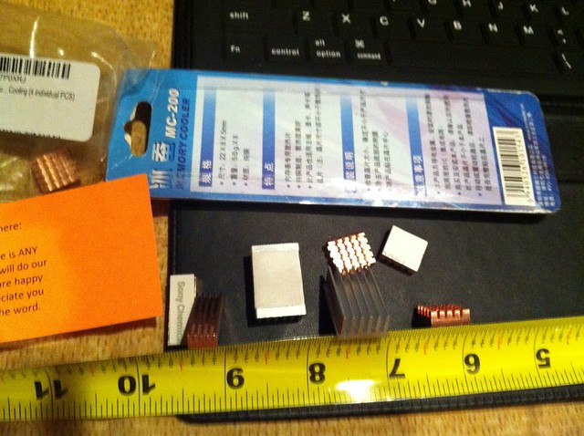
A good way to heatsink them is to take a pre 1982 US penny (or if there are any copper canadian coins) or a similar piece of copper and cut it into a square about the width of the chip. About an eighth of an inch from one of the side bend a 90 degree angle (this will take a strong vice). Lay it on top of the regulator (with some arctic silver under it if you want) with the bent edge facing down, so that it sits on top of metal tab of the IC. Solder it on to the tab and then use this copper piece to heatsink it (but it obviously has to be insulated from case neg now).
I don't have any real hard data saying that method is better than just heatsinking the plastic, but it seem logical to me that a metal to metal connection is going to be much better than metal to plastic even if it has to travel up that copper a bit first.