Welcome to Laser Pointer Forums - discuss green laser pointers, blue laser pointers, and all types of lasers

LPF Donation via Stripe | LPF Donation - Other Methods

Links below open in new window

ArcticMyst Security by Avery

Kryton buildling/fixing job

Joined
Feb 29, 2008
Messages
2,344
Points
0
I am at wits end with my kryton build, and I have realised that I have bitten off more than I can chew. I have a kryton here that I want to send to someone so that they can get it working, and so I dont have to continue throwing money at it. Is there someone (preferably in the UK) that I could send it to them , and they could look at what I have at the moment, tell me why it is wrong, and finish the build for me?

Thanks


daguin

0
Joined
Mar 29, 2008
Messages
15,989
Points
113
Post some pics and describe the problem. We might be able to get you up and running

Peace,
dave
 
Joined
Feb 29, 2008
Messages
2,344
Points
0
Ok thanks
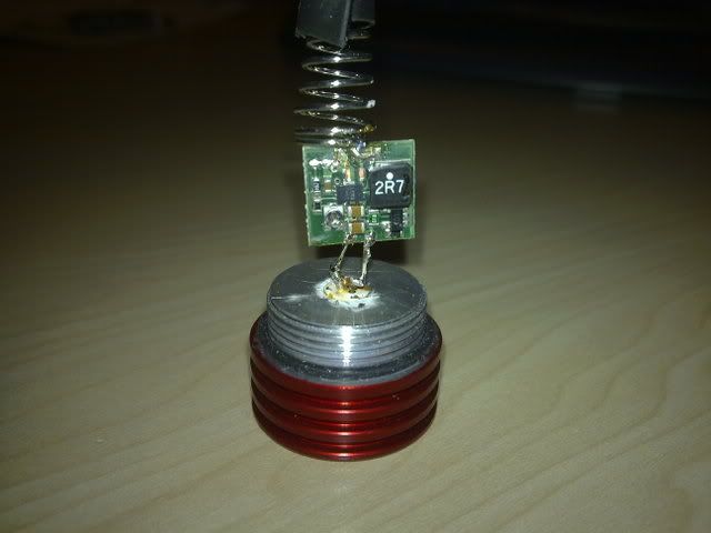
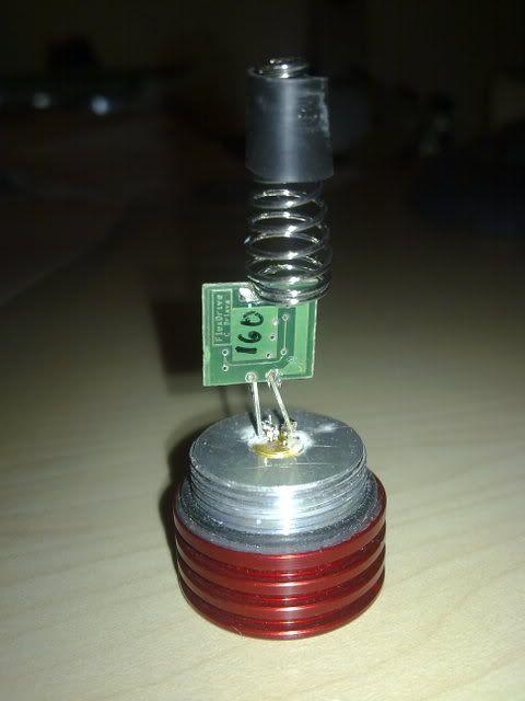
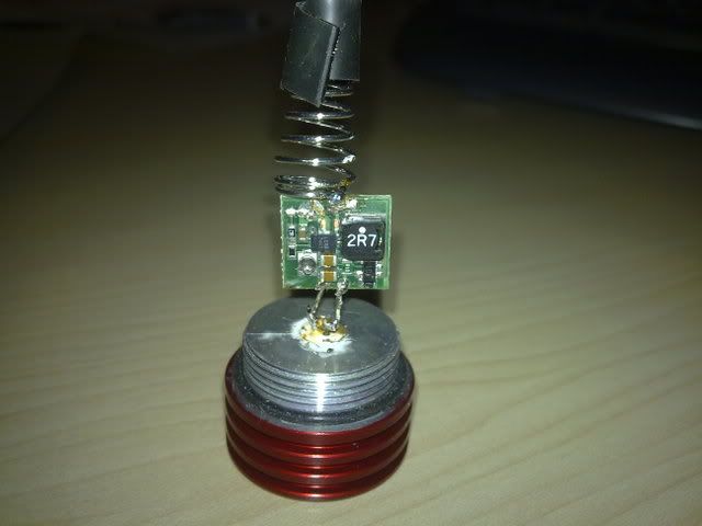
Image015.jpg

Image010.jpg

Image008.jpg


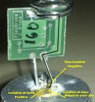
I soldered pins from a LED to connect the driver to the diode, as I found it hard to solder to the driver directly. The rubber on the spring is to stop it shorting. I soldered the - pin to the case pin, and then soldered it all up.
I'm not sure that these pictures will help, but I couldn't find a better camera
 

daguin

0
Joined
Mar 29, 2008
Messages
15,989
Points
113
Thank you

If you power the driver directly (not in the Kryton tube) does it lase?

Peace,
dave

[highlight]**EDIT** [/highlight]You can hook up power to the head/driver assembly just the way it is if you have a bench type PSU or just a battery and some wires to answer this question.
 

daguin

0
Joined
Mar 29, 2008
Messages
15,989
Points
113
robjdixon said:
No it doesn't lase at all

If powering the driver/diode in the head alone doesn't work then we have to ascertain if it is the diode, the driver, or both that are not working.

Do you have a test/dummy load and a DMM?

Unsolder the diode. Hook up the test load to the driver. Power the driver. Measure the output.

Peace,
dave
 
Joined
Jul 24, 2007
Messages
2,749
Points
0
Whilst you have the ld disconnected you could test that as well, set the DVM to "diode test" ( ->l- ) and connect it up, one way round should give you 0000 reconnect the probes the other way you should get a reading of 1.4 or there abouts.

If you get the above there is chance that the LD is good, if you get 0000 both ways it is a dead'un.

Regards rog8811
 

daguin

0
Joined
Mar 29, 2008
Messages
15,989
Points
113
STOP!!!

It appears from the pictures that the diode is hooked up with the polarity reversed.

On the flexdrive the positive is the side with the "2R7" on it.  The negative side is the side with the potentiometer on it.

Do you have the positive pin of the diode connected to the positive side of the driver? . . . Or is my perception just based in the way the picture appears?

Do you have the case pin soldered together with the negative pin?

Peace,
dave

blu-raypinout-1.jpg

[highlight]
**EDIT**[/highlight] Also, while you have it disconnected (and if it test out OK) we should do something about getting the diode pressed the rest of the way into the head
 
Joined
Jul 24, 2007
Messages
2,749
Points
0
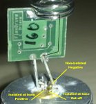
Looks right to me if the track I have put a black line on comes from the spring....which I assume is neg?

I will say I have not yet used a lavadrive (waiting for new ones to be available) so only a guess.

Regards rog8811
 

Attachments

  • Robj01_001.jpg
    Robj01_001.jpg
    61 KB · Views: 85

daguin

0
Joined
Mar 29, 2008
Messages
15,989
Points
113
It may be why I could not recognize it.  I was trying to see where the solder "blobs" tied to.  Your blow-up brings up another question then.

Is the negative pin actually cut off and not connected?  The negative pin and the case pin must be soldered together AND connected to the negative side of the driver

Also, the spring (which makes the battery connection) in this build should be positive.

Peace,
dave
 
Joined
Jul 24, 2007
Messages
2,749
Points
0
Just noticed Dave, you are assuming Blu ray, I am assuming red......which is it Rob (or have I just missed it....goes back to re-read ::) )

Regards rog8811
 

daguin

0
Joined
Mar 29, 2008
Messages
15,989
Points
113
rog8811 said:
Just noticed Dave, you are assuming Blu ray, I am assuming red......which is it Rob (or have I just missed it....goes back to re-read ::) )

Regards rog8811


;D ;D ;D ;D ;D ;D ;D ;D ;D ;D ;D ;D ;D

Perceptive filters rear their ugly heads once again

;D ;D ;D ;D ;D ;D ;D ;D ;D ;D ;D ;D ;D

I have no idea which it actually is.

It MUST be a violet laser, right?

I mean REALLY . . . who would build a red Kryton unless it was just part of a matched set?

Is that my A** showing? :-[

Peace,
dave
 
Joined
Feb 29, 2008
Messages
2,344
Points
0
Really sorry, it is a blu-ray, and the negative pin is connected to the ground pin. I'll check the driver tomorrow.

This is kind of in the wrong section now isn't it? ;D
 

daguin

0
Joined
Mar 29, 2008
Messages
15,989
Points
113
robjdixon said:
Really sorry, it is a blu-ray, and the negative pin is connected to the ground pin. I'll check the driver tomorrow.

This is kind of in the wrong section now isn't it? ;D


OK -- Just to clarify

blu-ray diode

negative and case pin soldered together

negative and case pin soldered to the negative side of the driver

positive pin soldered to the positive side of the driver

spring soldered to the positive side of the driver

no solder "bridges" between negative and positive contacts

If all that is valid, then we await the test of the driver and diode

Peace,
dave
 
Joined
Jul 24, 2007
Messages
2,749
Points
0
spring soldered to the positive side of the driver
Is that the way it is on the lavadrive?
If so I am totaly confused...does the track I have marked come from the spring? if so it goes to the case of the LD and, according to rob, is linked to the neg pin......

Regards rog8811
 

Attachments

  • Robj01_002.jpg
    Robj01_002.jpg
    63.4 KB · Views: 108


Top