LPF Donation via Stripe | LPF Donation - Other Methods
Links below open in new window
ArcticMyst Security by Avery


You are using an out of date browser. It may not display this or other websites correctly.
You should upgrade or use an alternative browser.
You should upgrade or use an alternative browser.
FS: Sonar Laser Cases!
- Thread starter Murudai
- Start date


drlava
0
- Joined
- Mar 7, 2007
- Messages
- 1,152
- Points
- 0
brtaman said:Hey drlava,
Are you using a flexdrive with your sonar build, or the new 1v drop linear one? Based on what we have found out up to now, it would seem the linear one would be ideal with 2x3.6 123 batts, if they fit.
Thanks
brtaman
I'll be using a single rechargeable and a dummy with the FlexDrive, or 2 primaries.. Haven't decided. With the single rechargeable, the runtime should be similar to using 2 rechargeables and a 1V linear, but much less heat is generated with the FlexDrive. Using 2 lithium primaries with the Flex should last almost forever
") Oh and the 1V drop Groove is not new, it's been around since the Fusion...
Oh and the 1V drop Groove is not new, it's been around since the Fusion... - Joined
- Dec 26, 2007
- Messages
- 682
- Points
- 28
Thanks so much for the compliments guys, I wish the HSs were easier to build, there are quite a few of the Sonars around, it turns out.drlava said:Beautiful build, guys, thanks a milion dark_horse for designing and machining these. Together with the driver people now have a laser that's better than the $2000 original
I am not Dave, but did you find the little piece of double-sided tape with the button, that should have worked.Just curious, dave, how´d you secure the button in place?
Nice building guys!!
BTW, you will definetly need a tail-cap spring, WL did not feel they owed you one I guess, it is at least a fairly common size (3/8" dia)
DH
Thanks to Dark_Horse for making these great heatsinks!
And thanks to me for starting the trend of Sonars in DIY ;D ;D ;D
Can't wait to build mine. I need a FlexDrive and a dummy battery. Can't afford it though... But I will one day, then I'll have my own Sonar
And thanks to me for starting the trend of Sonars in DIY ;D ;D ;D
Can't wait to build mine. I need a FlexDrive and a dummy battery. Can't afford it though... But I will one day, then I'll have my own Sonar
Yeah, i found that double sided tape, but I wasn´t sure about how well that would work. Because I don´t want to loose my button
By now I´am pretty sure that I am going to do the 2x 3v primary approach aswell. And it won´t be hard to remove the diode to retrofit it for the 3.6v rechargeable + dummy.
ArRaY
By now I´am pretty sure that I am going to do the 2x 3v primary approach aswell. And it won´t be hard to remove the diode to retrofit it for the 3.6v rechargeable + dummy.
ArRaY
- Joined
- Apr 29, 2008
- Messages
- 1,562
- Points
- 48
rkcstr, take a look at what Dr.Lava said:rkcstr said:Oh, and hey Jimmy(mcjimthejim), is that wire going from the input - to the ouput -? Thats what it looks like and if so, its not necessary. The input and output have common ground (test with a multimeter, you'll see they're already connected), so you can just remove that. And if you're using an 803T, you can solder the case pin and the negative pin together to complete the battery negative to driver ground.
And those using DrLava's driver, make sure you put some type of insulation on the bottom of the board to prevent any shorting of the pads to the heatsink
That red wire goes from the case pin to the negative end of the driver.drlava said:you have to connect the battery - to the driver too!
And I put a piece of clear tape on the bottom of the heatsink so no shorts for me!
daguin
0
- Joined
- Mar 29, 2008
- Messages
- 15,989
- Points
- 113
That red wire goes from the case pin to the negative end of the driver.[/quote]Jimmymcjimthejim said:rkcstr, take a look at what Dr.Lava said:
[quote author=drlava link=1209418066/360#362 date=1219772741]you have to connect the battery - to the driver too!
Your extra wire will not hurt anything. It is just not needed [highlight]IF [/highlight]you solder the case pin and the negative pin together. That way the case becomes the ground. If you look closely at the picture of my module, you will see that the only connection at the battery side of the driver is the voltage limiting diode.
Peace,
dave
rkcstr
0
- Joined
- Dec 1, 2007
- Messages
- 1,368
- Points
- 0
Yeah, I should assume most people are using the negative-insulated 803T diodes.
Basically, you get battery negative through the case. Now if you solder the case pin to the diode negative, you get battery negative to the ground on the driver without having to connect the input negative terminal.
The input negative and the laser diode negative terminals on the Lavadrive are common (shorted together), so you as long as one has a connection to battery negative (thru the case pin to heatsink to case to battery), it will work.
I just was pointing it out so you (and others) were aware... not that you need to remove it
- Joined
- Apr 29, 2008
- Messages
- 1,562
- Points
- 48
Oh. So if I connect the case pin to the negative pin, then I'll still have to connect the negative pin to the negative side of the driver?rkcstr said:Yeah, I should assume most people are using the negative-insulated 803T diodes.
Basically, you get battery negative through the case. Now if you solder the case pin to the diode negative, you get battery negative to the ground on the driver without having to connect the input negative terminal.
The input negative and the laser diode negative terminals on the Lavadrive are common (shorted together), so you as long as one has a connection to battery negative (thru the case pin to heatsink to case to battery), it will work.
I just was pointing it out so you (and others) were aware... not that you need to remove it
daguin
0
- Joined
- Mar 29, 2008
- Messages
- 15,989
- Points
- 113
Jimmymcjimthejim said:Oh. So if I connect the case pin to the negative pin, then I'll still have to connect the negative pin to the negative side of the driver?
Yes, but just on the diode side. The "extra" red wire isn't needed. It won't hurt (or even effect) anything. It is just extraneous (and two more solder joints to do).
Peace,
dave
- Joined
- Dec 26, 2007
- Messages
- 682
- Points
- 28
So I finished my build this morning, in about 30mins
I installed a Flex-drive in the same manner as Dave, with the diode for using 2-cr123s primaries, except I filed little slots into the diode-connection-holes, and the diode-pins plugged right in, a touch of solder and done. 3-total solder connections. I also "floated" the lava-drive on a dab of hot-glue.
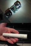
Like Dave, I believe the tail-cap is anodized for some WL-reason, (this make it non-conductive), it is almost like they never expected anyone to actually use these for a sucessfull-build. I "flat-sanded the end of the tube very carefully with some fine-sandpaper, and used an emery-board to carefully sand around the flange on the tail-cap, and then I sanded in the inside of the hole where the spring goes, and then, it came to life. I could not seam to set my little Cannon-camera to a setting that would yield a decent beam-shot.
Hey Dave, I think that yours may the very first-ever DIY Sonar and the most powerfull ever as well, quite a distinction
DH
I installed a Flex-drive in the same manner as Dave, with the diode for using 2-cr123s primaries, except I filed little slots into the diode-connection-holes, and the diode-pins plugged right in, a touch of solder and done. 3-total solder connections. I also "floated" the lava-drive on a dab of hot-glue.
Like Dave, I believe the tail-cap is anodized for some WL-reason, (this make it non-conductive), it is almost like they never expected anyone to actually use these for a sucessfull-build. I "flat-sanded the end of the tube very carefully with some fine-sandpaper, and used an emery-board to carefully sand around the flange on the tail-cap, and then I sanded in the inside of the hole where the spring goes, and then, it came to life. I could not seam to set my little Cannon-camera to a setting that would yield a decent beam-shot.
Hey Dave, I think that yours may the very first-ever DIY Sonar and the most powerfull ever as well, quite a distinction
DH
- Joined
- Dec 26, 2007
- Messages
- 682
- Points
- 28
Kenom
0
- Joined
- May 4, 2007
- Messages
- 5,629
- Points
- 63
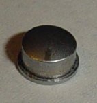
These are soo sweet. Not as good as my barrels are going to be but still sweet. I don't care for teh way the button mounts into place. it's just entirely too easy for it to come loose. would be much easier to use something like this that has a lip that stays on the inside of the barrel.
Attachments
rkcstr
0
- Joined
- Dec 1, 2007
- Messages
- 1,368
- Points
- 0
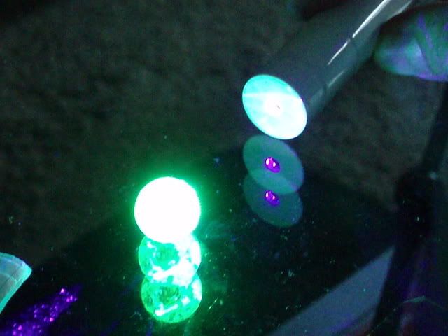
Thought I'd post a pic of the magic glowing sphere that came along with the cool case and awesome heatsink ;D
Sorry it´s me again, but did anyone exept dave drill out the front aperture cap? I don´t think it looks good with it drilled out.
Also, I would love to see a ~ 2mm blueray beam. That´d be nice! But I´am quite sure that this wont be easy to achieve without designing a custum diode/ lens system.
ArRaY
Also, I would love to see a ~ 2mm blueray beam. That´d be nice! But I´am quite sure that this wont be easy to achieve without designing a custum diode/ lens system.
ArRaY
daguin
0
- Joined
- Mar 29, 2008
- Messages
- 15,989
- Points
- 113
ArRaY said:Sorry it´s me again, but did anyone exept dave drill out the front aperture cap? I don´t think it looks good with it drilled out.
Also, I would love to see a ~ 2mm blueray beam. That´d be nice! But I´am quite sure that this wont be easy to achieve without designing a custum diode/ lens system.
ArRaY
The choices that I see are:
1) drill it out so it can be focused as needed
2) focus it to infinity and leave it there (under the aperture cap)
3) leave the aperture cap off and have the front of the unit exposed
4) remove the aperture cap every time you want to focus it
This was a compromise between wanting to preserve the "look" of the host and my practical needs. I chose to drill it out because, in practice, I need to refocus the beam for different uses. Drilling it out allows that to happen without needing to remove the aperture cap AND it preserves the "look" of the host as much as possible without sacrificing that need.
Peace,
dave
