

M3tal
0
- Joined
- Dec 9, 2010
- Messages
- 42
- Points
- 0
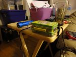
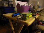
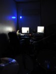
Here it is! Several days of drilling, cutting, soldering, gluing, trial-and-error & lots of swearing and it's finally done.
Hotlights blue host from
Rkcstr v3
SF AW210 405nm
1.5-12v 300mA voltage selectable DC power supply @12v
Miscellaneous parts
My plan is to eventually get batteries & install a charging circuit inside the Warheads tin.
I realize the design is overly complicated, but it's my first build and I wanted to have fun with it... :na: plus I've been dying to find a use for these really nifty key switches I have lying around.
Turn on the toggle switch and the red LED starts flashing to indicate standby... then as soon as the key is turned the green LED comes on to indicate the laser is ready for action.
Trouble is, I really don't know what kind of output I'm getting. I started with the pot at its lowest setting and have been slowly increasing power. I can tell you that when tightly focused it will light a match with a green head in about 5 sec. To test for heat I let it run for 30 seconds with the lens off & turn it off, then when I touch the top of the module it feels a little warmer than body temp. Can anyone give me a ballpark estimate as to the output?
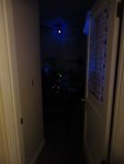
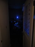
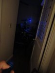
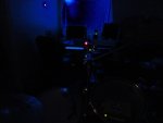
No matter what I tried I just couldn't get a beam shot... I guess the camera I'm using is not very sensitive to this wavelength but I can see the beam fairly easily in a dark room.
Thanks to Greg at Stonetek, Modwerx & everyone who has helped me out so far. I still have a 20x LPC-815 still in sled that wants to get out...
Hotlights blue host from
Rkcstr v3
SF AW210 405nm
1.5-12v 300mA voltage selectable DC power supply @12v
Miscellaneous parts
My plan is to eventually get batteries & install a charging circuit inside the Warheads tin.
I realize the design is overly complicated, but it's my first build and I wanted to have fun with it... :na: plus I've been dying to find a use for these really nifty key switches I have lying around.
Turn on the toggle switch and the red LED starts flashing to indicate standby... then as soon as the key is turned the green LED comes on to indicate the laser is ready for action.
Trouble is, I really don't know what kind of output I'm getting. I started with the pot at its lowest setting and have been slowly increasing power. I can tell you that when tightly focused it will light a match with a green head in about 5 sec. To test for heat I let it run for 30 seconds with the lens off & turn it off, then when I touch the top of the module it feels a little warmer than body temp. Can anyone give me a ballpark estimate as to the output?
No matter what I tried I just couldn't get a beam shot... I guess the camera I'm using is not very sensitive to this wavelength but I can see the beam fairly easily in a dark room.
Thanks to Greg at Stonetek, Modwerx & everyone who has helped me out so far. I still have a 20x LPC-815 still in sled that wants to get out...


 oke:
oke: