Welcome to Laser Pointer Forums - discuss green laser pointers, blue laser pointers, and all types of lasers

LPF Donation via Stripe | LPF Donation - Other Methods

Links below open in new window

ArcticMyst Security by Avery

Screwy Pot Driver Amperage

Joined
May 15, 2012
Messages
320
Points
28
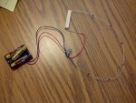
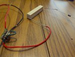
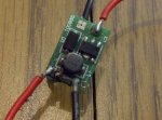
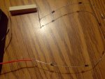
So I've been on this 2 year quest to build a blu ray laser into an altoids canister, and I did all my research and everything. My build so far is attached.

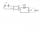
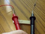
I'm using a dummy load as seen here all over the web: Laser Driver Set-up - OdicForce Lasers Online Shop

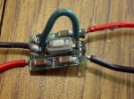
My driver is one of these (with voltage boost): 405nm 100 300mW Laser Diode Driver Reverse Protection | eBay

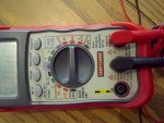
Now I've run into the problem of setting the current. I followed the instructions on the dummy load sites explicitly, and I'm finding that my driver gives me only 0.50mA, but testing over the resister as the instructions say, I get nothing: no voltage and no current. Here's the catch; the same driver that I just tested on the dummy load burned out a PHR803T diode on 1.5v at the same setting - probably 300mA. I know I saw another person on the forum with the same problem, but am I just an idiot, or does anyone know what my major malfunction is?
 

Attachments

  • Untitled.png
    Untitled.png
    11.3 KB · Views: 186
  • IMG-20130313-00702.jpg
    IMG-20130313-00702.jpg
    129.2 KB · Views: 218
  • IMG-20130313-00703.jpg
    IMG-20130313-00703.jpg
    112.5 KB · Views: 266


Joined
Oct 26, 2007
Messages
5,438
Points
83
While it does appear you wired it correctly to the dummy load in the photos (assuming red = +; black = -), your diagram depicts the wrong polarity connected to your diode. The + should go to the anode; the - to the cathode. See this diagram. As such, you might want to check if you've miswired with respect to polarities in the circuit itself. That 0.5mA reading sounds like the current is being outright blocked.
 
Last edited:
Joined
May 15, 2012
Messages
320
Points
28
While it does appear you wired it correctly to the dummy load in the photos (assuming red = +; black = -), your diagram depicts the wrong polarity connected to your diode. The + should go to the anode; the - to the cathode. See this diagram. As such, you might want to check if you've miswired with respect to polarities in the circuit itself. That 0.5mA reading sounds like the current is being outright blocked.

Indeed. But I did test the diodes the other way, and got the same result
 
Joined
Oct 26, 2007
Messages
5,438
Points
83
You do have the leads of your multimeter plugged into the correct terminals right?

I remember having to TA a class and that was one of the biggest problems people had.

Maybe take a picture of your exact test setup too.
 
Joined
Sep 20, 2008
Messages
17,622
Points
113
Like BB said... Show us a closeup of the Driver showing
the wires attached and also a closeup of your DMM showing
the selector switch and probes plugged in for your test.

As BB stated if the Red wire going to the Diode is +V then
the diode is blocking your current flow.


Jerry
 
Joined
May 15, 2012
Messages
320
Points
28
I know the driver looks pretty beat up, but I have an identical one hooked up to a burnt out diode
 

Attachments

  • IMG-20130313-00705.jpg
    IMG-20130313-00705.jpg
    141.1 KB · Views: 214
  • IMG-20130313-00707.jpg
    IMG-20130313-00707.jpg
    110.3 KB · Views: 200
  • IMG-20130313-00708.jpg
    IMG-20130313-00708.jpg
    111.8 KB · Views: 175
  • IMG-20130313-00709.jpg
    IMG-20130313-00709.jpg
    117.8 KB · Views: 377
Joined
Oct 26, 2007
Messages
5,438
Points
83
It looks like you have things soldered up correctly.

Just to make sure, when you're measuring current the driver is putting out, you're doing so by measuring the voltage across the resistor, and not using the current-measurement mode like the meter depicts in the 4th photo, right?
 
Last edited:
Joined
May 15, 2012
Messages
320
Points
28
It looks like you have things soldered up correctly.

Just to make sure, when you're measuring current the driver is putting out, you're doing so by measuring the voltage across the resistor, and not using the current-measurement mode like the meter depicts in the 4th photo, right?

Oh, yes, I was just trying every possible way to figure things out. I also get 0 volts across the resister. Here's what happens. Between LD+ and LD-, I have 7v. LD+ to behind the first diode gives me 70mv. LD+ to behind the 5th diode gives me like 30mv. And then all the sudden across the resister there is no voltage at all.
 
Joined
May 15, 2012
Messages
320
Points
28
Praise Thor, I've done it. I switched out my dead driver for the one in a previous build. Then I flipped the diodes so that the silver band is pointing toward LD-
I'm gonna leave this up for those having trouble with these adjustable drivers ^.^
 

Attachments

  • IMG-20130313-00710.jpg
    IMG-20130313-00710.jpg
    135.7 KB · Views: 199
Last edited:


Top