Welcome to Laser Pointer Forums - discuss green laser pointers, blue laser pointers, and all types of lasers

LPF Donation via Stripe | LPF Donation - Other Methods

Links below open in new window

ArcticMyst Security by Avery

My first PHR build.

Brett

0
Joined
Nov 28, 2008
Messages
177
Points
0
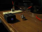
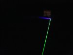
Well, I put together a 405nm labby with a diode I bought a while ago off of ebay. I paid a bit too much for this diode (before I had the "brilliant" idea to check the group buys) so I am quite glad I didn't kill this one with heat, too much current (yet..heheh), or by shearing off the pins. This was my first blu-ray/violet/UV 405nm project, and I've been excited about finally getting to see this color displayed in an impressive coherent form. I wasn't disappointed. I used an LM317 driver (in fact, one that was still on the proto-board from another project), and threw in the only resistor I had that was close to what I think is the right spec....a 20ohm. My pot was a 25ohm, so I was kind of worried about having too limited a range of trim for the current, but when I applied power, everything was fine.

Oh, and let me back up. I used an Aixiz module pressed into a Z-bolt heatsink, which had just arrived in the mail a couple days ago. Very nice heatsink by the way, it's inexpensive, and I highly recommend it. I think Dave, ElektroFreak and a few others use this as well. I followed Styropyro's Guide on harvesting diodes and inserting them in the module. I was pretty sure what to do, but his guide was helpful in keeping my eagerness at bay so I wouldn't get in too much of a hurry and ruin the only diode I have right now for 405.

It is a real testament to the knowledge and cooperative spirit of the people on this forum that I was able to so easily make my first 405nm build a successful one. Thanks everyone!


Attachments

  • 405_labby_002.jpg
    405_labby_002.jpg
    772.8 KB · Views: 81


daguin

0
Joined
Mar 29, 2008
Messages
15,989
Points
113
Congratulations!

It's purty, ain't it?

Peace,
dave
 

Brett

0
Joined
Nov 28, 2008
Messages
177
Points
0
405nm photography is damn difficult! the conditions outside are perfect (super foggy with drizzle) and the beam is visible for over 100 feet, but I just can't seem to get a picture of the blu-ray beam that comes even close to representing the brilliance of what the naked eye sees. It's like the camera sees the first 20% or so of the beam and then it just drops out to nothing. I guess I'm just going to have to get a fog machine and do some of these shots in the garage.

I meant to mention in the first post. The biggest problem I have right now is that my Fluke 12 multimeter doesn't measure current...only voltage, capacitance, resistance, and diode check. I have an amp clamp, but it only does large currents and doesn't go down to the mA resolution. Naturally this makes me afraid to crank the pot up on the driver. I have a laserbee on the way, which will tell me the power output....but it would be more precise to have a proper milliammeter. I'll have to dig out my old radio shack analog meter, I think it has dc ma up to 250.

Here's a picture of my Aixiz green labby and my PHR labby. You can see the truncated beam appearance here that I was talking about.

-Brett


Attachments

  • beamshot405_532.jpg
    beamshot405_532.jpg
    733.4 KB · Views: 76

Brett

0
Joined
Nov 28, 2008
Messages
177
Points
0
daguin said:
Congratulations!

It's purty, ain't it?

Peace,
dave

It sure is...I was very excited, and my wife was actually impressed with this one too. It didn't hurt that purple is her favorite color either.

-Brett
 
Joined
Feb 21, 2008
Messages
1,056
Points
0
You can still measure the current flowing through your diode.  Put a one ohm resistor in series with the diode. Measure the voltage across this resistor when the laser is running, the voltage in millivolts will equal the current in milliamps. A fluke is a good meter, this one ohm resistor is a good idea for those of us who have to use a cheap dollar store DMM that may not be accurate at all when measuring current.

EDIT - Amp clamps are typically for measuring AC current only.
 
Joined
Sep 20, 2008
Messages
17,622
Points
113
Hey Brett.... like "billg519" said... the best way to measure current would be to use
a 1 Ohm resistor and measure the voltage across it (1mV=1mA)... This way the
connections to the diode are solid....

If you put a milliamp meter in series with your diode and any one of the 2 plugged
meter leads is just slightly loose or intermittent... you can kiss your 405nm LD
goodbye... :'(

Just my $0.02

Jerry
 

Brett

0
Joined
Nov 28, 2008
Messages
177
Points
0
Yeah, I wanted to use the 1 ohm resistor technique, but with all the dozens of resistors I have in my drawer, I don't think I have a 1 ohm. I guess it's time to get a Digikey order ready, since I also need some 100ohm pots and all the Radio Shacks in my area are bad about keeping their parts stocked. They care mainly about selling cell phones...it's sad what's happened to Radio Shack since the early 80's when I was a kid and first playing around with electronics.

-Brett
 

Kage

0
Joined
Mar 5, 2008
Messages
285
Points
18
Nice work!

It's always good to see somebody NOT blowing up their first diode ;)


lasersbee said:
Hey Brett.... like "billg519" said... the best way to measure current would be to use
a 1 Ohm resistor and measure the voltage across it (1mV=1mA)... This way the
connections to the diode are solid....

If you put a milliamp meter in series with your diode and any one of the 2 plugged
meter leads is just slightly loose or intermittent... you can kiss your 405nm LD
goodbye... :'(

Just my $0.02

Jerry

That's how my last dead 4X met it's end :-[
 

Brett

0
Joined
Nov 28, 2008
Messages
177
Points
0
Now that someone has finally posted again on my PHR-803t  thread, I can make an update without it being a double post. And Kage....Thanks for noticing I didn't blow it up (yet!).

I still don't know the current I'm dumping into that diode, but don't really care at this point....its already provided me with hours of fun and education, and I am currently guessing that it's been seeing between 75ma and 100ma, maybe a bit higher when I've dared to turn the 25ohm pot all the way up.  Currently have a 15ohm resistor in the circuit as well.  When I turn the lab lights off and turn up the pot a good distance, you can see the visible beam and spot intensify noticably, expecially the beam brightness is impressive.  With the lens turned most of the way, the thinnest part of the beam waist (focal point) is about 2 inches away from the aperture.  At that point it can easily light a match, but how long it takes depends on the setting of the 25ohm potentiometer.  The variation is from about 14 seconds on a low setting, to around 500ms on the highest (which I'm afraid to try very often since I don't have a current measurement).

Right now I don't have any replacement diodes, and this one has about 4 or 5 hours of continous use on it since I put it together a few days ago.  My laserbee is on the way, and I'd love to not kill this one before I get my 5 sleds that are coming from one of the group buys.  One of the most exciting parts of this hobby (and really anything where you play with engineering, electronics, high voltage, etc) is quantification and taking comparitive measurements.  It's that thrill of being able to make the leap from just making educated guesses about what's going on, to finally being able to actually *know* at least on of the parameters.

Any way you look at it, blu-ray lasers are a lot of fun!  Especially for the low effort and cost involved.

Oh, and one more thing I did to my setup shown in the first pic.  I added a large (I think around 160uf 100v) cap to the input of my LM317T drive to allow reduced ripple input from a 9v wall adapter.  Burns great and steadily!!!

-Brett
 
Joined
Feb 21, 2008
Messages
1,056
Points
0
Assuming the LM317 driver ... With the pot set at 0 ohms, and the resistor being 20 ohms, your diode should be seeing about 62 ma. With the pot at 0 ohms and the resistor being 15 ohms, the diode should be seeing about 83 ma. You should be very safe at these current levels. If you could come up with some resistors in parallel that give 11 ohms, with your pot set at 0, you would give the diode about 113 ma, this seems fairly safe with PHR-803T's. With the pot at max, and the 11 ohm resistor, you would give the diode about 34 ma, which would be right around, or just below its threshold. Hope this helps a bit.
 
Joined
Dec 6, 2008
Messages
1,581
Points
63
Brett;

My first 405 worked too...
 until I turned it up to far. :(

billg519 has given you the 83ma for a 317 current regulator with 15 ohms .

One thing I would caution you on:

the breadboard is not a secure connection to the LD.

If you temporarily lose the connection, the voltage will increase and may damage the LD when it regains contact.

Solder the connections.

LarryDFW
 

Brett

0
Joined
Nov 28, 2008
Messages
177
Points
0
LarryDFW said:
Brett;

My first 405 worked too...
 until I turned it up to far. :(

billg519 has given you the 83ma for a 317 current regulator with 15 ohms .

One thing I would caution you on:

the breadboard is not a secure connection to the LD.

If you temporarily lose the connection, the voltage will increase and may damage the LD when it regains contact.

Solder the connections.

LarryDFW


Larry,

Thank you for reminding me of the potential instability of the breadboard.  Actually I've been worrying about it more or less constantly any time I have to move something like the heatsink (containing the laser) around with its attached leads.  I have some copper clad Radio Shack experimenter's boards I will put to use either tonight or tomorrow.  

Bill,

Initially, I stated that I had put in a 20 ohm resistor.  After doing some research and calculations I switched it out to a 15 ohm.  It's nice to see that your math shows 83ma max.  I've been scared to turn it up longer than a few seconds.  

Thanks to everyone who has given advice on this thread.  This forum is the greatest.

-Brett


Top