Welcome to Laser Pointer Forums - discuss green laser pointers, blue laser pointers, and all types of lasers

LPF Donation via Stripe | LPF Donation - Other Methods

Links below open in new window

ArcticMyst Security by Avery

Advice for a beginner

Joined
Dec 10, 2009
Messages
8
Points
0
Ok, my blu-ray laser refuses to turn on. I have a complete circuit and have tested the battery and its still good, I have checked for shorting and used tape as I thought necessary. As far as I can tell it should be working fine.

Any theories or suggestions would be much appreciated. If you need me to post anything else I would be more than happy to do so. :bowdown:

Thanks in advanced,:beer:
CS


Joined
Jun 12, 2008
Messages
1,199
Points
48
Hate to be the bearer of bad news, but it is quite possible that the LD has decide to call it quits.

Though, this may not necessarily be the case. Can you give a bit more detail, as to the driver being used, which LD is it, what current was it run at, how much time has it been running?
 
Joined
Jan 7, 2007
Messages
6,309
Points
83
OK, so you say you have a complete circuit. How much current is it drawing?

HMike
 
D

Deleted member 8382

Guest
you should make some checks:

1.-Does it emit any light at all?
2.-Is it drawing current from the batteries? (use a MM for this one)
3.-Are the batteries at full charge?
 
Joined
Jan 7, 2007
Messages
6,309
Points
83
Sometimes the Noobs seem to speak a different language. Never a mention of a DMM.
I still don't understand the use of "OK" at the beginning. Seems something is not OK if it isn't working.

HMike
 
Joined
Dec 10, 2009
Messages
8
Points
0
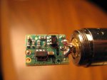
I have attached a picture of the flexdriver. Also, I spoke to a friend who showed me that I was using the voltmeter wrong.:yabbem: Anyway he showed me how to use it correctly and I have discovered that I don't have a complete circuit, but I still cant figure out which part is broken.

The picture is labeled as follows,
1.Is the positive power connection
2&3.I am fairly sure are microcomputer
4.Is the negative diode and case pins
5.Is the positive diode pin.

I set my voltmeter to beep when it has a circuit. According to it I have circuits as follows,
1 connects to 2 and 3 on various pins.
1 and 5 do not connect.
4 and 5 do not connect ether.
But 5 connects to the negative power pad (below 1)

I have absolutely no idea if any of this is relevant, but I am willing to do anything to get this laser working.

Thank you,
CS
 

Attachments

  • IMG_0108.JPG
    IMG_0108.JPG
    77.7 KB · Views: 122

daguin

0
Joined
Mar 29, 2008
Messages
15,989
Points
113
It is difficult to see with your circles and numbers on the picture. Also please show both sides of your driver. At this point, I am most interested in seeing your solder job at the diode pins

Your diode needs to be pressed in farther. It should be "recessed" a bit. This will NOT effect whether it lights or not, but it will effect whether you can focus it or not.

Since you were using your DMM incorrectly, how did you set the current? How much current is it set for??

When you are "testing" it to lase, where are you connecting the power leads? What voltage are you using?

After you answer these questions, we may get you back on track.

Peace,
dave
 
Joined
Dec 10, 2009
Messages
8
Points
0
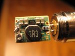
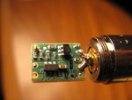
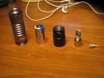
I am assuming by DMM you are talking about the flexdrive??(the board in the middle) It is currently set to 115 mA and it was preset when I ordered it. Per the tutorial at I-Hacked.com Taking Advantage Of Technology - Building a High-Power Blu-Ray Laser I attached a spring to the positive power pad. The spring was cold soldered on and came of and a decided not to touch it. And I am fairly sure it is a 3V battery. I attached a picture of my whole setup.

CS
 

Attachments

  • IMG_0107.JPG
    IMG_0107.JPG
    194.3 KB · Views: 96
  • IMG_0108.JPG
    IMG_0108.JPG
    185.8 KB · Views: 100
  • IMG_0114.JPG
    IMG_0114.JPG
    213.6 KB · Views: 96
Joined
Jul 1, 2009
Messages
588
Points
18
I am assuming by DMM you are talking about the flexdrive??(the board in the middle) It is currently set to 115 mA and it was preset when I ordered it. Per the tutorial at I-Hacked.com Taking Advantage Of Technology - Building a High-Power Blu-Ray Laser I attached a spring to the positive power pad. The spring was cold soldered on and came of and a decided not to touch it. And I am fairly sure it is a 3V battery. I attached a picture of my whole setup.

CS

from the 2nd picture it seems that the case pin isn't connected anywhere.you should solder it with the positive or negative,depends on how you will use it.to use the battery neg side facing tail cap(how it was used when it was a flashlight) solder the case pin on the pos and solder a spring or something to make contact with the battery to the neg pad.(CMIIW)
 
Joined
Dec 10, 2009
Messages
8
Points
0
From what I understand the problem seems to be that power is not getting from the positive power pad to the positive diode pad. I don't see how removing that will help. Just looking for some clarification before I do it.

@daguin how would I seat the diode further in?

CS
 
Joined
Dec 10, 2009
Messages
8
Points
0
from the 2nd picture it seems that the case pin isn't connected anywhere.you should solder it with the positive or negative,depends on how you will use it.to use the battery neg side facing tail cap(how it was used when it was a flashlight) solder the case pin on the pos and solder a spring or something to make contact with the battery to the neg pad.(CMIIW)

The case pin is connected to the negative diode pin. And yes there is a spring that attaches to the positive pad on the flexdriver, it has fallen off and I didn't want to mess with it anymore than I needed to so I left it off. What do you mean by "pos" I am very new at this and don't know any of the terms.

CS
 
Joined
Jul 1, 2009
Messages
588
Points
18
The case pin is connected to the negative diode pin. And yes there is a spring that attaches to the positive pad on the flexdriver, it has fallen off and I didn't want to mess with it anymore than I needed to so I left it off. What do you mean by "pos" I am very new at this and don't know any of the terms.

CS

positive.as mentioned above remove the stock driver and re-install the spring.
 

daguin

0
Joined
Mar 29, 2008
Messages
15,989
Points
113
I am assuming by DMM you are talking about the flexdrive??(the board in the middle) It is currently set to 115 mA and it was preset when I ordered it. Per the tutorial at I-Hacked.com Taking Advantage Of Technology - Building a High-Power Blu-Ray Laser I attached a spring to the positive power pad. The spring was cold soldered on and came of and a decided not to touch it. And I am fairly sure it is a 3V battery. I attached a picture of my whole setup.

CS

First - on the positive diode pin, is there any solder or other metal bridging (connecting) the pin and the case. The positive pin MUST be isolated from the case.

Second - Have you tested this OUTSIDE the host? Connect the positive lead to where the spring would attach and the negative lead to the module case. You can use a battery and wires for this step. This will tell us if it works before placing it into the host.

Third - Is the solder that you have on the positive "hole" (where you connected the spring), bridging onto the pot?

Fourth - Are you using flux? Your solder joints do not appear to have flowed well. There is no end to the problems cold joints can cause you. Use flux and pre-tin connections.

Peace,
dave
 
Last edited:


Top