Welcome to Laser Pointer Forums - discuss green laser pointers, blue laser pointers, and all types of lasers

LPF Donation via Stripe | LPF Donation - Other Methods

Links below open in new window

ArcticMyst Security by Avery

8X Diode Murder fund

IgorT

0
Joined
Oct 24, 2007
Messages
4,177
Points
0
I've been running my 8x on 300ma and it doesn't get hot at all. I'm buying another host... the 18650 one and I want to increase it to at least 390ma. The beam isn't really all that visible in its current state but it burns like hell and damnation itself. It even burns without being completely focused. The beam on my dilda is brighter than it is.

It doesn't even get warm for me. I have it in the side button host right now.
Again... no heat.

Heat? What does heat have to do with anything?


Heat is NOT what kills diodes, CJ! If you go by heat you'll kill your diode in no time (and you wouldn't be the first to do that - i've heard of people turning up the current while feeling for heat with their fingers)!

What kills diodes is their own optical output power - the light they produce, and it's effect on the end facets of the diode (optical flux at the die burns up the mirror, if it finds a weak spot - an imperfection, which then starts spreading and growing exponentially, eventually resulting in COMD, aka Catastrophic Optical Mirror Damage).


Heat only makes them age faster, but when i say heat, i'm talking about temperatures at which you couldn't even hold the laser in your hand!

Also, heat has the worst effects in constant power setups (like in drives, because the hotter the diode (= lower efficiency), the harder it has to be driven to maintain the required power level).

In lasers, where we use constant current, heat actually reduces the stresses on the diode (but only by a tiny bit), by reducing the optical flux at the die, since efficiency drops, while the current stays the same....

In fact, hot diodes can survive higher currents than cold ones, because cold they will produce more optical power at those currents.. Allmost every diode i killed died cold at a powerup, when their power is the highest and the powerup stresses push it over the edge...


From what you're saying, i am guessing you:
1. don't have a meter
2. stumbled upon a VERY SHORT wavelength 8x diode!

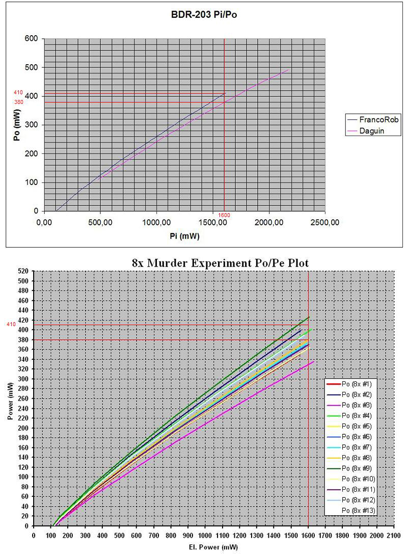
I found the 8x's to vary quite a bit in wavelength, and incidentally, one of the highest efficiency ones displayed the shortest wl. of the bunch (altho i only started doing relative wavelength measurements from 8x diode #5 - i'll do the first four later, i forgot at first)...


390mA is absurd! I'm sorry to have to say that, but they are dying at 360mA already, and not from heat. Besides, without a meter you don't even know it's efficiency, you might even have a freak on your hands... But whatever it's efficiency, i don't think 390mA is a good idea (If you really want to get rid of it that bad, send it to me instead... :angel:).


The reason i'm guessing it's a short wavelength, is because you said the beam of your dilda is brighter... BluRays usually have MUCH more visible beams outside at night, but a spot of a red does look brighter, and under some conditions (mist, fog) so can the beam of a red (- seem brighter, altho at the same time, the BluRays are still somehow more visible even tho the color itself is darker).


I think you should have someone meter your laser first, and if you REALLY HAVE to push it, consider a power at which at least some are surviving, like 360mA for example (even tho i'm not setting mine that high unless a miracle happens during testing - and it would have to be a VERY impressive miracle!)...
 
Last edited:


Joined
Aug 31, 2009
Messages
2,157
Points
0
I'm glad you told me that. I had already asked Jayrob to set it to 350. And you're right, I don't have a meter.

I also asked Jayrob to set the solder jumpers, on the flex drive, to the 155-600ma range so that I can change the current, within my choice, if I need to. Any suggestions on a good LPM?


EDIT: I just messaged Jayrob to set the current at 320ma. I think you're right IgorT about the wavelength. When I shine it at white cloth it is a super bright pure blue dot that is blinding. I'll wait for your testing to raise it higher. I think 320 is ok for now. Please correct me if I'm wrong
 
Last edited:

IgorT

0
Joined
Oct 24, 2007
Messages
4,177
Points
0
I'm glad you told me that. I had already asked Jayrob to set it to 350. And you're right, I don't have a meter.

I also asked Jayrob to set the solder jumpers, on the flex drive, to the 155-600ma range so that I can change the current, within my choice, if I need to. Any suggestions on a good LPM?

EDIT: I just messaged Jayrob to set the current at 320ma. I think you're right IgorT about the wavelength. When I shine it at white cloth it is a super bright pure blue dot that is blinding. I'll wait for your testing to raise it higher. I think 320 is ok for now. Please correct me if I'm wrong


I think we are pushing these poor diodes too far as it is, but then again, we all want more power... :yh:

So while i'm a little worried, i'll still set both of mine to somewhere between 280-320mA (to compensate for efficiency differences). But i wouldn't go higher than that, at least until i see the experiment results...


In any case, 320mA is WAY more reasonable than 390mA... So if you want to push it, go with that for now... (Did anyone ever even set one to 390mA?)

If you also manage to get your laser metered, that would be even better, cos then the results of the first experiment would be easier to apply to your diode (if it's efficiency was known)...


Otherwise, everything you're describing sounds like you stumbled onto a shorter wl. diode.. It happens... I didn't expect 8x's to vary as much as GGWs, but now i saw they do, and i heard from several people, they feel shorter wl's burn better at the same powers. And fact is, they do cause more fluorescence..

I do not recall seeing a beam that would be lower in visibility than a red tho, even when i made an ultra-short wl. 6x on request (for special purposes - it was later measured as 399nm), the beam would still be visible outside at night.


As i said, under some conditions, a red beam does look brighter. But somehow not necessarily more visible. Only the color is brighter-looking, that's all.
But if you look at a red and a blu beam from a 90° angle, the blu always looks more visible. At least as far as i can remember...

I should check with some ultra short wl. diodes i am saving for special requests...


A good LPM? I'd have to say, go with the LaserBee...

It's more than good enough for hobby purposes (i found them to be very accurate through some measurement comparisons) and i believe the price to be very reasonable... I've made a few LPMs, but it's a lot of work (i especially dislike mounting everything into an enclosure, or rather cutting the holes for it), so i think it's great of Jerry to offer them to laser hobbyists at an affordable price!


As for the Murder Experiment...

After talking to Dave, i decided to stay at the 300mA we decided on for the first diode.

Dave told me his first 8x produced "only" 440mW at 370mA! Our first winner would produce 455mW at 370mA, so it would seem some diodes simply exhibit such low efficiencies, and i was worried for nothing...


I am however interested in what became out of that first 8x...

Dave?
 
Last edited:
Joined
Aug 31, 2009
Messages
2,157
Points
0
I didn't expect 8x's to vary as much as GGWs, but now i saw they do, and i heard from several people, they feel shorter wl's burn better at the same powers. And fact is, they do cause more fluorescence..

I have these little 6mm green airsoft bbs and they shine like nothing else with my current 8x. Plus silly string loves to shine too. My curtains and pillow brightly shine as well.

When I focus the beam as straight as I possibly can it still burns.

I can't wait for the real green and blue diodes to come out. What a day that would be.
 
Joined
Feb 1, 2008
Messages
2,894
Points
0
IgorT,

So... just so I can better understand what you're saying,

if two diodes were plotted against each other, output power vs. current. Would.. the diode with a larger slope be better off at 320mA, than the diode with a smaller slope?

Or do voltages need to be considered as well, since the diode's voltage is needed to determine it's actual efficiency?
 
Joined
May 14, 2008
Messages
468
Points
0
IgorT:

#529: Wow, Igor, beautiful work and plots!:beer:
It looks that these diodes show a wider Pi/Po (efficiency) range with respect of the two BDR-203 diodes (Dave and mine ones) shown in my datasheets... I have replotted these data putting into evidence the 1600mW Pi line (but recorded with I = 290mA), while your plots are with an I = 280mA.

4079529305_86efc82b93_o.jpg


#538: Concerning Hemlock Mike diode degradation, I understood it was another one respect what I recorded in my datasheets.... this is why I didn't change his data....
 
Last edited:

IgorT

0
Joined
Oct 24, 2007
Messages
4,177
Points
0
I can't wait for the real green and blue diodes to come out. What a day that would be.

Indeed, but i fear the cheapest way for us to get them will be to rip appart laser video projectors.. And since they will use low power diodes, we will have to look for high resolution "big screen" laser projectors (since they will require much more laser power).

Otherwise, 455nm diodes already do exist, but they cost $800 a piece for 10pcs MOQ ("sample order").. GB anyone? :whistle:

It would be awesome having 100mW of 455nm!
Assuming they can be overdriven just like the 405nm diodes.. Cos the $800 ones are rated for 50mW CW..

Question is, who would be brave enough to overdrive an $800 diode to their rated pulsed power...


Nichia also has 455nm diodes, altho theirs cost $2000 a piece. But they give a big discount if you buy 100! Only $1600 a piece (IIRC - the numbers are approximate from what i remember)...


I'm afraid the only high power diodes we are ever gonna see relativelly "cheap" are the ones we get from drives.. What i would not give to have a friend in a sled manufacturing factory... :angel:

Altho i'm guessing eventually laser show manufacturers will also get to use blue and green diodes... Evidently they get 405nm diodes at decent prices, altho question is if it's through official channels (the Nichia LD from a laser show manufacturer was a floating pin, which are meant for drives)...


BACK ON TOPIC:


A photo of my "Diode Torture Chamber"...

Well, it's not much of a "chamber" really (yet), it's all just naked circuitry for now, i won't have the time to dress it up as nicelly as my LPM or Diode Analyzer any time soon.. :undecided:
But it doesn't have to be pretty, to kill diodes... :evil:


It just shows the main parts of the setup - took a picture during the preparations and testing..

You can see the Cycler circuit at the bottom. It's a very simple circuit which just turns a relay ON and OFF...

On a separate board is a switching power supply. It is set for approx 3.6V out, like a Li-Ion, in order to power various Buck/Boost drivers. But it can be set higher, to power linear drivers too, the blue multiturn pot adjusts the output voltage, which is then toggled by the relay on the first circuit.

This way, everything - including the laser being tested - runs off the same power supply...

Alternativelly, the relay can also be used to toggle external power sources, in case the number of diodes being tested at once exceeds the switching PSU's abilities...


On the top is the counter. All it does is count the number of times it's input is toggled..
In this case it is toggled by the photo-transistor you can see on the left.
Connected together, the counter counts the number of times it detects light..


Since i was worried about an accidental power outage, i added a secondary time recorder, but it turns out it won't be needed, as the counter has 50h of data memory..
If anyone is interested, you can see it's "datasheet" HERE. Still, a backup doesn't hurt - it's a Chinese counter... :whistle:
For some reason, they used a red wire for negative and a black wire for positive power input! I almost killed it when first hooking it up! :thinking:

The counter can go up to 99999 counts, which translates into almost 1667 hours using 1 minute ON time, which is WAY more than we need. The backup time recorder on the other hand can go much further than that.


While it's not in a pretty box, everything is ready to run, but there is one last thing i am working on..

The photo-transistor is too sensitive. It detects everything, from a light being turned ON to me walking by and casting a shadow on it..
Because of that i am making it a nice little sensor enclosure, which will protect it from ambient light sources.

The photo-transistor is hidden in a small box, with a hole covered by a diffuser - the photo transistor is behind the diffuser. Leading to that hole will be a short plastic tube, with a black inner wall, so that light coming from other angles can't get in either directly, nor through reflections...

The beam will have to hit the diffuser through that tube, so the laser and the sensor will both be on one stand, holding them aligned.
This completelly elliminates any other light sources from influencing the setup.


Anyway, here is the picture for now...
The next picture will be of the setup in action... :yh:
 

Attachments

  • Cycler & Counter.JPG
    Cycler & Counter.JPG
    146.9 KB · Views: 115

IgorT

0
Joined
Oct 24, 2007
Messages
4,177
Points
0
IgorT,

So... just so I can better understand what you're saying,

if two diodes were plotted against each other, output power vs. current. Would.. the diode with a larger slope be better off at 320mA, than the diode with a smaller slope?

You're asking about efficiency, which determines how steep the slope is...

Let's say we have two diodes, one puts out more, the other less power at the same current.
My guess, based on some testing and experience is, that the lower efficiency diode would die sooner than high efficiency ones when set to the same current.

I can't say that for sure, i have not killed nearly enough diodes to proove that. But with 6x's for example, practically all normal or high efficiency ones are surviving 190-200mA (in experiments or out in the "wild"), while several low efficiency ones died at those same currents - some in as little as a few hours!


Problem is, the first GGW sleds were of questionable origin. They were sold to us as QC rejects, but there is some evidence they were actually prototyping rejects. Because of that i can't say the results are conclusive, besides it would take killing more diodes than any of us can afford to be able to say this for sure..


There are many factors involved, when it comes to how long a diode will last. And it's quite complicated to imagine it all...
For example. Diodes eventually die from being "worn out" by their own optical flux. The higher the optical flux at the die, the faster a diode will burn out. But it also depends on the die itself, or rather the amount of imperfections on it...

A high efficiency diode will produce more power at the same current, than a low efficiency one.
So from this aspect, the high efficiency one will be under more "pressure" than the low efficiency one.

But there must be a reason for the efficiency difference..

In a diode, the die has to be "perfect" in order for a laser diode to work at all. Of course nothing can be perfect, but they have to be near perfect to work...

Any imperfections will absorb light, instead of reflecting it out. If that starts happening, it will create a "hot-spot". And the imperfection will start growing exponentially. Once it becomes big enough, the result will be instantaneous - the diode will commit COD.

So when i assume that low efficiency diodes are weaker, not only in terms of power they put out, but in terms of how much they can survive, it is because i am assuming, that the efficiency difference comes from the diode having more pre-existing imperfections.


And if that assumption is correct, that a low efficiency diode produces less output, because it has a "less perfect" die, on one hand, it will produce less optical flux, it will put less "pressure" on itself. But on the other hand, it will have more imperfections which their optical flux can exert "pressure" on...

A high efficiency diode will produce a higher optical flux at the die if it's powered with the same current. But if efficiency is a result of die imperfections, it has less imperfections that could start absorbing instead of reflecting light. So on one hand, it puts more "pressure" on itself, on the other, it is likelly it is capable of surviving the higher amount of "pressure", and would last longer at the same current.


In any case it is surelly a balance - one puts itself under more stress, but might be more capable of withstanding it, the other puts itself under less stress, but might be less capable of withstanding it - but which way the balance will tip is hard to say. However i usually bet on the higher efficiency diodes.


On the other hand, if you set two different efficiency diodes to the same power, the higher efficiency one will require less current to reach it.

In this case the answer is much easier:
- High efficiency diode = same optical flux + lower current
- Low efficiency diode = same optical flux + higher current

If efficiency variations are the result of imperfections, at the same power, the higher efficiency diode would live longer, since it needs less current to reach it, and is likelly more capable of withstanding it.


But keep in mind that the above mentioned experiences came from GGW sleds which likelly contained prototyping rejects.

There many diodes were used that were not capable of actually working in a 6x drive even for a short time!


Here all diodes are tested, and the variations are MUCH lower - all of them would work thousands of hours in a drive powered to a specific power instead of with constant current...

And all of them are meant to produce the same power while writing in a drive, regardless of their efficiency.


So except for that one diode that was REALLY low in efficiency, i am not worried about the rest. In fact the second winner is already a normal 8x dode, and killing that one will produce VERY interesting results, better applicable to others!


Or do voltages need to be considered as well, since the diode's voltage is needed to determine it's actual efficiency?

See, this is what i'm wondering about myself..

Until recently, i only used slope efficiency to sort diodes, i did make full PIV plots, but to determine which are high or low in efficiency, i just used the mW per mA plots...


But then as i tested more and more GGW diodes, writing all the data in my diode notebook, i would look at it sometimes, and notice BIG variations in their forward voltage...

And normally, i started wondering, if it means anything, if it has an impact on how much the diodes can take.

For example, if one diode needs more current to reach the same power, but requires less voltage to reach that current, it could actually be more efficient, than a diode that reaches a higher power at the same current, but needs more voltage for that current to flow!


This is why i used Po/Pe plots to compare these 8x's.. And in some cases, the order actually was reversed, in others diodes that would previously stand appart suddenly overlapped, others again stood further appart after being plotted against their input power...


But which is more important, input current or input power, i really can't say..

Current and voltage BOTH matter, when it comes to the actual efficiency - how much of the power coming in comes out in the form of light, and how much in the form of heat..

But i'm already assuming that efficiency differences are related to diode "health"..

Where the Vf differences come from, i have no idea..


The manufacturers declare diodes by their slope efficiency - mW per mA...

I sorted them using mW per mA data so far, and had good results, altho Vf differences are usually small, and might not make themselves noticable even if they matter.


Figuring out if they DO matter would be a VERY expensive experiment.


The only thing i know for sure is that it matters when it comes to actual diode efficiency and the heat created.

It might also matter when it comes to their life expectancy, but i really don't know, there is so much guessing involved already.... :undecided:
 

IgorT

0
Joined
Oct 24, 2007
Messages
4,177
Points
0
IgorT:
#529: Wow, Igor, beautiful work and plots!:beer:
It looks that these diodes show a wider Pi/Po (efficiency) range with respect of the two BDR-203 diodes (Dave and mine ones) shown in my datasheets... I have replotted these data putting into evidence the 1600mW Pi line (but recorded with I = 290mA), while your plots are with an I = 280mA.

Thank you Franco!

I was thinking about adding data from other diodes into the plots to make a nice collection, but i only have data for ONE other diode....

You actually have full plots for several... Together with these, they would make a very nice compilation!


As for the 280mA limit in my tests, it's only temporary..

The first two diodes were plotted up to 360mA! With the rest i decided to be more gentle, and so i ended the plots at 280mA - the plots done in 40mA steps.

This gives me enough info to be able to extrapolate 320 and 360mA, both in power AND forward voltage (altho the latter is a bit trickier, but required for the Po/Pe plots), and as soon i have the time, i will post plots going up to 360mA for all diodes..

I already prepared a new Excel sheet calculating the power steps, to help me see their behavior, and calculate the higher numbers..

I also made slightly improoved plots, which make it easier to discern different diodes..


But it's gonna have to wait until the work is done.
 
Joined
Aug 31, 2009
Messages
2,157
Points
0
Hey IgorT... I don't know if this would help you but so far my 8x is doing just fine at 300ma's. I tend to turn it on and off a lot and it burns white paper instantly. No sign of decreased brightness yet.
 

Krutz

0
Joined
Nov 21, 2007
Messages
1,733
Points
48
about efficiency and imperfections:
until now we were only speaking about imperfections on the facet, which increase and accumulate and all. shouldnt we be able to see either more scattered, diffuse light from the die, or dark areas on the facet, when there are such imperfections? speaking about differences in the 10% range, this wouldnt be much to detect, of course. but maybe it would yield some interesting results to look at a de-canned diode for scatter with a phototransistor or something, and have a look at the facet (off axis angle!) under a microscope with low optical output? a nightmare, thinking about the eye-risk!

if that all doesnt lead to anything, the impurities have to be in the cavity.. but then low-efficiency diodes shouldnt die earlier, when at the same thermal stress?

manuel
 

HIMNL9

0
Joined
May 26, 2009
Messages
5,318
Points
0
For example, if one diode needs more current to reach the same power, but requires less voltage to reach that current, it could actually be more efficient, than a diode that reaches a higher power at the same current, but needs more voltage for that current to flow!

This is why i used Po/Pe plots to compare these 8x's.. And in some cases, the order actually was reversed, in others diodes that would previously stand appart suddenly overlapped, others again stood further appart after being plotted against their input power...

But which is more important, input current or input power, i really can't say..

Just a personal consideration, so, take it for the few that it may worth ..... thinking about the differences in your plots, give me an idea .....

Supposing, just as example, having two diodes that have the same PO and current, but different VF at that PO / current ..... needing less voltage for have the same current, means, basically, that the LD chip have a lower resistance, and consequently, that is pushing out the same power, but dissipating less of the input power in heat, so the efficency is better ..... (after all, the current is a result of voltage and resistance, and the heat dissipation also depend from this, so, less VF with the same current, means that the LD chip is "eating" less power for produce the same output)

I think the better way that you may use for judge the efficency, in fact, is the PI / PO report ..... less PI with more PO is the best ;)
 
Joined
May 14, 2008
Messages
468
Points
0
HIMNL9:
well, everybody knows the Ohm law V = RI, so IMO your supposition is right. Unfortunately only three members, of the eighteen "declared" owners of a 8x BR, have been able till to-day to supply PIV data relevant to their products (you can easily check it giving a look to #2, #3 and #4 of the 8x BR DIODES topic)... they are Dave (Daguin), Igor (IgorT) and Larry (LarryDFW). Thanks to Igor, only now we have other 13 Pi/Po plots: it's a very good database in addition to the other initial four diodes. (Thanks Igor :yh: for your BIG work)! All the general plots of the first graph in #1 were just to give a graphical reference datum to the owners, as in the "LPF Forum - 8x DIODE USERS" datasheet the current and the Po are already recorded....maybe in the future (if other members agree) I'll implement only the list....

IgorT:
YOU have done a big work:beer:, my "several" are only four....:undecided:; I'm very interested to see your next improved plots, where it will be easier to discern different diodes, as it will be for sure a must in the future, it is quite impossible to add more Pi/Po curves in one graph if one is willing to distinguish one from the others.... and we are speaking only of the 8x! Can you imagine to plot also the efficiency of all the PHR and the 6x you and other members have manufactured, in case all PIV data would be available?
For statistical purposes I'll be happy to continue to implement the "8x Users" datasheet if the new members supply me of the minimum data...., for example now I know that Crazy Jay is a happy owner of another 8x: if he will be so kind to tell me some more data (like those recorded in the datasheet), I'll be happy to add him to the list.....
 

HIMNL9

0
Joined
May 26, 2009
Messages
5,318
Points
0
^ Totally agree about the big work that IgorT is doing ..... perhaps we have to offer him at least a beer ..... at least :beer:

Also, you're right about the possibility to give data ..... build a test set is easy, but make also all the work of testing, collecting data and organizing them, it require a lot of time ..... i had planned to do something similar, in the past days, but, apart the fact that i don't have 8X diodes, just 6X, now i'm working at home too (rebuilding a floor, repainting walls and windows, pulling cables, and some other little things like these ones :p), so, the expression "free time", actually, lost any sense, for me :p
 
Last edited:

IgorT

0
Joined
Oct 24, 2007
Messages
4,177
Points
0
Hey IgorT... I don't know if this would help you but so far my 8x is doing just fine at 300ma's. I tend to turn it on and off a lot and it burns white paper instantly. No sign of decreased brightness yet.

Oh, i'm afraid you won't notice degradation with your eyes..

Besides, many people have their 8x's at 300mA or more for months without problems... Only problem is, estimating the actual use is hard..


Otherwise, degradation is really hard to notice, even with a meter.

I usually mostly observed it with PHRs, which i burned REALLY hard! I was leaving them ON for 30-60 minutes at once every day (that was before i had the cycler).


Also, PHRs were under 200mW so i was able to measure them in 0.1mW resolution... That's 10 times the resolution i have above 200mW! Well, my first GGW was also under 200mW, it started out at 193mW..


With degradation it was like this.. It would start out as a feeling that i'm seeing slightly lower numbers on the meter (i metered them very often, so i got a feeling for how they behave).

In almost every case i blamed it on temperature differences at first. And im talking about SMALL power drops, like 0.5mW at first. Even tho my meter is a little more jumpy in that resolution (obviously - it detects every smallest movement or air current in front of it) i would somehow know my lasers and how the numbers "behave" when measured...

And the power would drop in the smallest fractions of a mW, more and more, until it would peak 1mW lower than i was used to...

At this point i was usually still hoping that it's just because the ambient temperature was higher, but then it was 2mW less, and soon 3mW less, and then i couldn't find an excuse anymore and had to face the fact that my diode is degrading. Especially when my IR thermometer confirmed that i'm measuring them at same temperatures...

The most painful part was watching my first GGW degrade.. It used to peak at 193mW, suddenly it was only 190mW. Then one day 193mW again, and i was excited i thought it didn't degrade afterall, but then 189, 188, 187, less and less, until it ended up at 184mW - this was almost after a year of HEAVY use (and abuse).

It would probably have lasted a while longer, but i set it to a higher current, where it produced over 260mW after the medium custom lens..

In the end it expired when i gave it to a local buyer, to make it easier for him to wait on his own laser... At that point i expected it to die and had a good replacement waiting, so i was almost happy i could convert my main personal laser to the latest version with a very special GGW diode.


In any case, under normal circumstances degradation is slow. I mean consider your use. It is minutes per day at most. It takes a while for hours to pile up. Here i will have to be much more careful, checking every two or three hours, to see how soon it starts and how fast it progresses..

Every so often i will interrupt the experiment, let the laser cool to a predetermined temperature, and check it's power to see if and how much it dropped. I hope to be able to make a graph of degradation over time.

If i understand correctly, it should not degrade linearly, but exponentially. So recording it at fixed intervals could yield interesting results, perhaps even help figure out an approximate percentage of power a diode can lose before enough defects accumulate to make it commit COD.


EDIT:
ACTUALLY IMPROOVED PLOTS


Since the previous plots were a "little" messy, with many diodes overlapping and hiding others of similar or same efficiency behind them, i tried improoving them a little, using thinner lines and different colors on a slightly different background... It's still not possible to discern every diode, but i'll make separate plots anyway.

A couple of participants asked for better plots, so here they are, it's as good as i can make it in a group. GB participants will each get their own with a full "datasheet" including Ith, slope efficiency, actual efficiency and two or three different graphs.


Everything is the same as before, except that the lines are thinner, and some colors are changed, in some cases i had to switch them cos it turned out similar colors were overlapping. It's a little easier to tell them appart now, but some are still very close together.


P.S. Otherwise i finished the sensor housing a bit earlier (it's suddenly immune to shadows, lights, even flashlights shining directly into it, only lasers make it triger now) and i'm starting up the cycler. Pics in a bit! :yh:


EDIT: Damn, i set JPG compression to a minimum, hoping they would be as clear as i see them in Excel, but no such luck... :undecided:
The colors are still mixing and the improovements i thought i made are not really all that obvious...


EDIT 2: Ok, i used the .PNG graphics format for the screen cap, i knew that the quality would be better, but i expected the files to become larger.

Surprisingly the files are now one quarter the JPG size, but the colors are not blurred out anymore.

I hope now it's easier to discern individual plots, additionally, i reduced the scale of X and Y axis, since not all plots are extrapolated to 360mA yet anyway...
 

Attachments

  • 8x Murder Experiment P-I Plots.PNG
    8x Murder Experiment P-I Plots.PNG
    100 KB · Views: 111
  • 8x Murder Experiment Po-Pe Plots.png
    8x Murder Experiment Po-Pe Plots.png
    99.7 KB · Views: 112
Last edited:
Joined
May 4, 2009
Messages
5,443
Points
113
Very cool a pictue Thanks !


Indeed, but i fear the cheapest way for us to get them will be to rip appart laser video projectors.. And since they will use low power diodes, we will have to look for high resolution "big screen" laser projectors (since they will require much more laser power).

Otherwise, 455nm diodes already do exist, but they cost $800 a piece for 10pcs MOQ ("sample order").. GB anyone? :whistle:

It would be awesome having 100mW of 455nm!
Assuming they can be overdriven just like the 405nm diodes.. Cos the $800 ones are rated for 50mW CW..

Question is, who would be brave enough to overdrive an $800 diode to their rated pulsed power...


Nichia also has 455nm diodes, altho theirs cost $2000 a piece. But they give a big discount if you buy 100! Only $1600 a piece (IIRC - the numbers are approximate from what i remember)...


I'm afraid the only high power diodes we are ever gonna see relativelly "cheap" are the ones we get from drives.. What i would not give to have a friend in a sled manufacturing factory... :angel:

Altho i'm guessing eventually laser show manufacturers will also get to use blue and green diodes... Evidently they get 405nm diodes at decent prices, altho question is if it's through official channels (the Nichia LD from a laser show manufacturer was a floating pin, which are meant for drives)...


BACK ON TOPIC:


A photo of my "Diode Torture Chamber"...

Well, it's not much of a "chamber" really (yet), it's all just naked circuitry for now, i won't have the time to dress it up as nicelly as my LPM or Diode Analyzer any time soon.. :undecided:
But it doesn't have to be pretty, to kill diodes... :evil:


It just shows the main parts of the setup - took a picture during the preparations and testing..

You can see the Cycler circuit at the bottom. It's a very simple circuit which just turns a relay ON and OFF...

On a separate board is a switching power supply. It is set for approx 3.6V out, like a Li-Ion, in order to power various Buck/Boost drivers. But it can be set higher, to power linear drivers too, the blue multiturn pot adjusts the output voltage, which is then toggled by the relay on the first circuit.

This way, everything - including the laser being tested - runs off the same power supply...

Alternativelly, the relay can also be used to toggle external power sources, in case the number of diodes being tested at once exceeds the switching PSU's abilities...


On the top is the counter. All it does is count the number of times it's input is toggled..
In this case it is toggled by the photo-transistor you can see on the left.
Connected together, the counter counts the number of times it detects light..


Since i was worried about an accidental power outage, i added a secondary time recorder, but it turns out it won't be needed, as the counter has 50h of data memory..
If anyone is interested, you can see it's "datasheet" HERE. Still, a backup doesn't hurt - it's a Chinese counter... :whistle:
For some reason, they used a red wire for negative and a black wire for positive power input! I almost killed it when first hooking it up! :thinking:

The counter can go up to 99999 counts, which translates into almost 1667 hours using 1 minute ON time, which is WAY more than we need. The backup time recorder on the other hand can go much further than that.


While it's not in a pretty box, everything is ready to run, but there is one last thing i am working on..

The photo-transistor is too sensitive. It detects everything, from a light being turned ON to me walking by and casting a shadow on it..
Because of that i am making it a nice little sensor enclosure, which will protect it from ambient light sources.

The photo-transistor is hidden in a small box, with a hole covered by a diffuser - the photo transistor is behind the diffuser. Leading to that hole will be a short plastic tube, with a black inner wall, so that light coming from other angles can't get in either directly, nor through reflections...

The beam will have to hit the diffuser through that tube, so the laser and the sensor will both be on one stand, holding them aligned.
This completelly elliminates any other light sources from influencing the setup.


Anyway, here is the picture for now...
The next picture will be of the setup in action... :yh:


Top